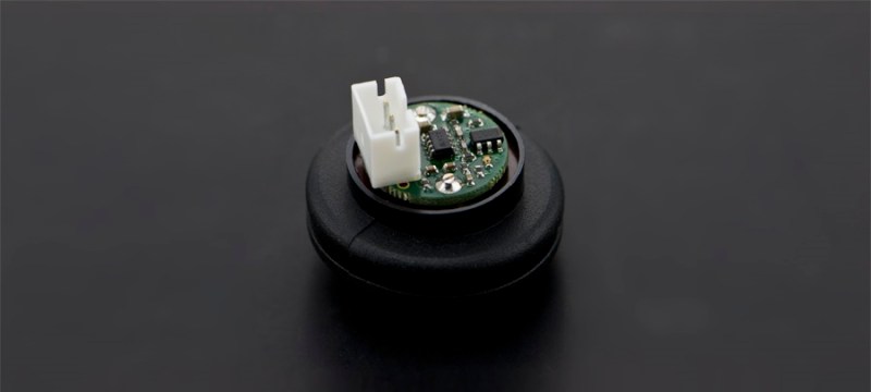
The SRF01 is a popular ultrasonic sensor used primarily for range finding applications. [Jaanus] discovered that they had a few flaws, including not working after being dropped. The faulty ones began to pile up, so he decided 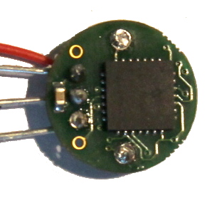 to tear one apart and put his engineering skills to use.
The SRF01 is unique in that it only uses a single transducer, unlike the SRF04, which uses two. Using only one transducer presents a problem when measuring very close distances. The transducer emits a pulse of sound and then must listen for the echo. The smaller the distance, the smaller the time interval between the pulse and when the echo returns. There is a fundamental limit to this time as the transducer has to recover from what is known as ringing. [Jaanus] discovered that the SRF01 solves the ringing problem with the use of a PIC24’s ADC and its 500 ksps (kilosamples per second) rate. This allows it to measure very close distances.
Be sure to check out the teardown for more details on how the SRF01 works.


Nothing on why it seems to break from being dropped?
That’s what I clicked through on the article for, too :-/
Also I wonder why it has a fixed 70ns ping and not dynamic, pinging immediately after it receives an echo…
what if it never receives the echo?
Then there is no object or it is more than the ~6m max away. Just as already is the case.
i have made geophones from large diameter speakes before and the sensitivity would be so high that one needed to short circuit the transducer to ground before attempting to move or handle them or the amplifier stage would blow.
perhaps these suffer from similar issues with their transducer, a sudden enough shock could overload the amplifier, i have no idea if this even applies to these transducers, just a thought.
that makes a lot of sense since it uses a piezoelectric transducer.
Wouldn’t a TVS diode solve that ?
perhaps, but they do tend to act like (very small) capacitors and that can present problems with small and/or fast signals, truth be told i would probably try if i ever were to build one again, since the local noise of various activity tends to bleed out anything that would be masked by that small capacitance, in reality it isnt as much of a drawback as it would initially seem, due to the sensitivity you cant be in the immediate proximity of them while running your experiment to begin with.
The reason for the fixed ping rate is the max range. when you ping faster, an echo of a far away object can be detected just after the new ping was fired, and the sonar will erroneously think something is closeby. in short, for each ping you have to wait for the *possible* echos of the previous one to have died out.
This is the nyquist limit in effect.
Ping too fast, and you don’t know is you’re coming or going, if you are just beyond max range or minimum range.
Of course, if you know the penetration distance of your emitted pulse, you can set your timing to max out at the maximum penetration. You can also put identification code in each pulse, but ultimately the higher your receiving:transmitting ratio the better (as an example, medical ultrasound purportedly aims for >99% receiving time, and some will sweep a 2D field several hundred times a second)
The simplest explanation for Nyquist criteria is that you need at least 2 points to fit a sine wave in the waveform you are collecting. So it follows that your sampling rate is at least 2X the frequency you are interested in.
This isn’t fitting a sine wave.
Right, you wait at most that max range (7ns). But why wait all that time out if the echo comes sooner?
You mean 70ms instead of 7ns? Sound wave are slow.
Yes
You could choose not to wait, but consider this case. You have a narrow object at two feet away, and a broad object at three feet. You do your first ranging, successfully detect the object at two feet, and decide to immediately start another ranging. But this time, you detect an object at one foot, because you’ve just received the echo from the object at three feet, and from the first ranging.
In some cases. you might be able to use the echo amplitude to determine which ranging the echos are from, but no guarantees. The object at three feet away, despite the greater distance, may due to its larger size present a stronger echo than the object at two feet.
Or for the second ranging, you could generate a different ping frequency than the first. And by detecting the frequency of received echos, determine which ranging an echo is from. But then you’re not taking advantage of the natural resonant frequency of the transceiver. You need more power on transmit, more amplification on receive. And that means a more expensive ranger.
I understand, but how is than any different than when it times out at 70ms (~6M) and an object is 6.1M away? Does the chirp naturally diminish enough at this distance to make it a physical max?
Yes. Or at least it’s such a weak echo that it cannot be confused for a close object, even if that object is quite narrow. It’s typical for a ultrasonic rangefinder to decrease its sensitivity after emitting the ping, then gradually increase it; so the 6.1M echo simply falls beneath the detection threshold on the subsequent ranging.
Of course, you can always come up with ways to fool it. Like placing a parabolic reflector at 6.1M, aimed back at the rangefinder. ;) That’s not something one finds in a typical environment, though. More of an issue are flat and smooth surfaces, within the detection range, angled in such a way that the echo doesn’t bounce back towards the rangefinder. It’s not a perfect measurement technique.
That’s a disappointment. Neither HaD nor the source site explain what was wrong with the device, nor how it was fixed.
Definitely needs a Part Two to explain the failure mode and describe the solution. One of the freebies I get in the email inbox is Design News’ “Made by Monkeys”, which are anecdotes from engineers describing puzzling faults they’ve encountered, the sometimes stupid reasons behind those faults, and any fixes. It definitely helps me to have insight into the fixit mindset, and read others’ diagnostic procedurals: http://www.designnews.com/archives.asp?section_id=1367&dfpPParams=bid_240&dfpLayout=siteInfo
Nice start to reverse engineering the rangefinder. A couple of thoughts:
1) That the ringing problem is solved *just* by sampling at a reasonably fast ADC rate is an oversimplification. Consider that the echo signal is many magnitudes smaller than the transmitted signal, *both* of which are fed into the filter/preamp. So you must make sure that portion can recover from saturation fast enough.
2) While it’s pretty likely the PIC’s ADC is being used, you can’t assume that with 100% certainty. This PIC has a peripheral crossbar (PPS) and can assign many different functions to any pin. It’s possible it might be using a comparator or timer in a clever way.
If a part two is coming, it would be nice to see the output of the filter/preamp scoped, with objects at various ranges. Which PIC pin that output goes to. As well as why it fails after being dropped, if that can be determined.
I have done a lot of reverse engineering and done my own design in my HaD contest entry, so I can share some of my thoughts. in the subject. My final design use separate transducers, but I have looked at using a single one. I have implemented both a range finder and a sonar mode that captures the echo analog waveform for playback.
There are tear downs, simulations and captured waveforms in a few of my log files.
https://hackaday.io/project/5903-sonar-for-the-visually-impaired/log/24845-firmware-progress-1-digital-range-finder
– I have implemented a variable threshold comparator using ADC peripheral. By putting the threshold outside the ringing, you can reduce the minimum detection distance. If the object is close, it’ll have a loud echo.
– You want to limit the gain so that the input isn’t saturated by the ringing. Reducing the amplitude of the sonar ping by reducing # of cycles into the transmit can possibly help a bit.
– I have tried on-chip analog comparator, but the DAC setting time and propagation delay means you cannot change threshold on the fly. This type of work needs to be done in digital domain.
– A special transducer with internal mechanical damping is needed for this. There is only so much you can do by adding resistor in parallel to the transducer. You don’t have the option for shorting the transducer for this case.
Could you feed the transducer with an antiphase signal at a reduced amplitude to dampen the ringing?
Actually tried that. I don’t remember if it was simulation only or in my breadboard. What I have observed is that for the first couple of cycles, the amplitude dies down half way and then it builds up again. It is bit hard to control the amplitude as I am driving it with logic gates – either a 3.3V p-p or 6.6V.
This is with both output grounded for 8 cycles and a 3.9k damping resistor Too much mechanical energy is stored in the transducer. As soon as the driver went tristate, the ringing goes again!
https://cdn.hackaday.io/images/4120371435341677434.jpg
There wasn’t much time to do it within the contest deadline, so I have to choose something that is most likely to work. The ultra cheap undamped transducer was not good enough for this, so I have settled for separate transducer. I ended up driving both outputs to ground until the next ping.
It is not usable for a single transducer design for down to 0 cm range. On the other hand, my application does not require 0 cm.
Forgot to say this: (my speculation)
There is a phase difference between the mechanical oscillation and electrical. So unless I compensate for that, just driving the transducer with 180 degrees offset won’t completely cancel out the oscillation. Now if there is a more intelligent algorithm that measure the phase and amplitude and dynamically adjust for it would work a lot better, but the complexity was beyond my alloted time and resource for that part of the project.
“The SRF01 is unique in that it only uses a single transducer, unlike the SRF04, which uses two.” Aerrrrgh! Yet another company assigning part numbers that make no sense. Would they stick SRF16 on a version with 4 transducers?