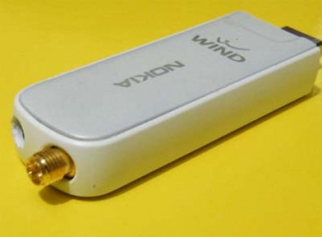
[Maurizio] was having some reception issues with his wireless internet and set out to add an external antenna to the USB dongle (translated). He had previously poked around inside of the Nokia internet key to find that the internal antenna was a flexible circuit substrate wrapped around a plastic box that made contact with main circuit board via a spring connector. This plastic frame is just right for mounting an SMA connector in just the right place for it to stick out the end of the case as seen in the picture above. It gives him better range, but since speed depends on how much traffic the wireless node is under, it’s not a guarantee that you’ll get a snappier connection after this hack.


Someone tell me how to do this with my brain. The reception lately has been a bit fuzzy.
Very nice hack, especially as 3G dongles with external aerial connectors are now as rare as hens teeth (presumably as part of manufacturer’s drives to reduce unit costs)
Unless I’m mistaken, these devices use specifically engineered strip line antennas. If you’re going to hang “stuff” off it, the usual rules of impedance matching apply. I’m wondering if he considered such things ? Unless it was engineered to avoid mismatches, signal gain might actually be less than the OEM design.
@Ed
Judging by the quality of the “hack”, I highly doubt he considered such an important issue. He doesn’t even mention the impedance of the coax cable that he so sloppily attached to the SMA connector. 100 bucks says that the performance of this “hacked” unit is overall lower than its unmodified counterpart.
You could say that this “hack” was “hacked” together by a “hack” ;)
Well I would say that most “external” antennas are matched to a 50 Ohm circuit so it is quite a safe bet to replace it like done here.
Not like the original connectors to have the antenna contact are very high quality.
With one connector only the input is balanced already so no further matching circuit is required.
there is more than ohm law in RF design, I bet the reception get worse after hack due to mismatch created
When I did research for my first cantenna, it was a recurring piece of advice that the ID of the cantenna be a factor of the wave height of your desired RF wave. So, when designing your cantenna it is recommended to make the ID 1/4, 1/2, or 1/1 of the size of the wave height to ensure proper reception. Do the same things not apply to the length of these types of external antennae?
Is it correct to assume that the length of those antennae that they include with your wireless AP and router are all the same length because it is a factor of the wave height of a 2.4GHz wave? Or was that just some coincidence because of manufacturing considerations?
You make a good point Malikaii. Even a quick Google search will show the correct way to design an antenna.
Personally I think the link between device form factor and frequency of operation is almost purely coincidence but may be linked a little.
There was always a drive for faster transmission rates, but just so happened the modern inventions of silicon integrated circuits, surface mount devices etc. This means we can build small devices, at around 1/4 wavelength of the high-speed signals. Of course, smaller components have also helped increase the speed of electronics too. The clock rate of processors in particular.
Really this can be a problem, not only a benefit! If you have a small electronic device (something not designed to work with RF), each trace inside becomes like a small antenna (1/4 wavelength of 2.4GHz is around 30mm). This noise can cause problems in the device, like wild operation of micro controllers and digital logic.
A little help to the non RF initiated.
Antenna matching is critial to ensure that the power sent to the antenna is not bounced back to the reciever.
Wikipedia link for more information
http://en.wikipedia.org/wiki/Impedance_matching
One great non electrical example from the wiki to get everyone thinking about this issue correctly.
“The gel used in medical ultrasonography helps transfer acoustic energy from the transducer to the body and back again. Without the gel, the “impedance mismatch” in the transducer-to-air and the air-to-body discontinuity reflects almost all the energy, leaving very little to go into the body.”
As shown in the following link, you could also build
one of the popular “kitchen strainer” antennas.
I´ve build two from cheap cake-protectors for my friends. Simple but boosting up their UMTS reception …
http://www.usbwifi.orconhosting.net.nz/
@Ed “..Judging the hack” dont worry, no ambition its only a cheap hack :)
@all … sorry:
cable was an RG 174 50ohm, but is not important ’cause it’s very short. (and not ground run around/along wire)
M.
If the antenna is store bought it’s probably 50ohms. The problem is a lot of strip line antennas or chip antennas are not 50 ohms. Thus there are matching networks before the antenna which transform the impedance from the amplifier to the antenna. These impedances could really be anything so the only way to know for sure would be to use a Network Analyzer. If you don’t have access to one you shouldn’t be hacking on anything over 1GHz unless the impedances are stated.