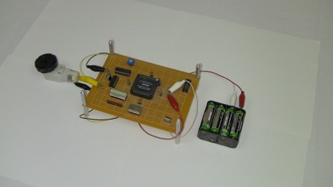
[Chris] continues cranking out the tutorials, this time around he’s showing how to use a CPLD for simple motor control. The demo hardware is pretty basic, he built his own FPGA/CPLD demo board a few years back which used a PLCC socket for easy interfacing. You should be able to use just about any gear you have on hand.
Of course the thing about these chips is that you’re working with hardware that can be run in parallel. [Chris] mentions that this is what makes it perfect for timing-critical applications. Here he’s using a motor driver that monitors a PWM signal, using the duty cycle to actuate the direction and speed at which the motor turns. After the break you can see a demonstration of the CPLD reading from an ADC chip and converting the value to a PWM signal. [Chris] has also used the same hardware for VGA signals; something that is usually a timing nightmare if done with a microcontroller.
If this leaves you thirsting for more CPLD goodness check out our own guide on the subject.


I’m not sure why a DC motor is time critical. Most of them really ‘eat’ anything you provide them with.
On the other hand… If you would do this with a BLDC motor without sensors (use the same leads to drive and sense), it might get a lot more interesting :-)
i know uC, but not so much CPLD…
inside the CPLD, can we specify resistors and capacitors??? or just logic gates???
Just logic gates
For those wanting to give CPLD a quick try there are actually a pic chip that has programmable logic gates, not near as many gates as a CPLD but the chips also has other features like a waveform generator and numerical controlled oscillator.
The chip is the 16F1508