When [101 Things] didn’t want to copy Morse code, he decided to build a Pi Pico system to read it for him. On the face of it, this doesn’t seem particularly hard, until you look at the practical considerations. With perfectly timed dots and dashes, it would be trivial. But in real life, you get an audio signal. It has been mangled and mixed with noise and interference as it travels through the air. Then there’s the human on the other end who will rarely send at a constant speed with no errors.
Once you consider that, this becomes quite the project, indeed. The decoder captures audio via the Pi’s analog-to-digital converter. Then it resamples the input, applies an FFT, and converts the output via a complex classification pipeline that includes, among other things, Bayesian decoding. Part of the pipeline makes simple typo corrections. You can see the device do its thing in the video below.
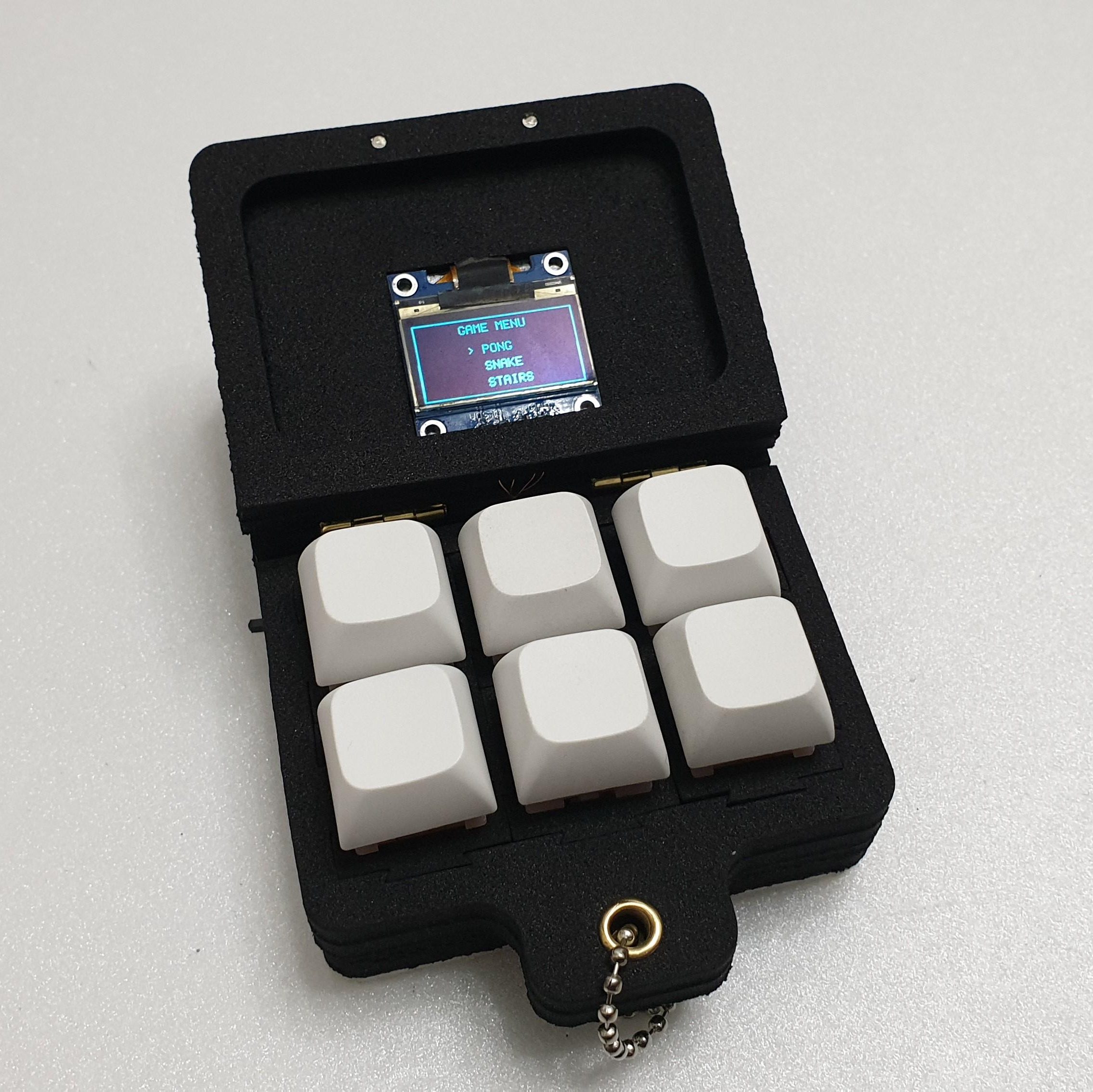
Fidget toys are everywhere these days. A particularly popular type simply puts some keyboard switches on a plate to provide a certain type of clicky satisfaction. [wjddnjsdnd] took that concept a step further, building a keychain-sized fidget toy that actually has games on it.
The build is based around six key switches in a 2 x 3 array. The key switches are notable in this case for being magnetic shaft keys. Rather than using a mechanical switch to indicate a keypress, the keycap instead merely moves a magnet which triggers a signal in a hall effect sensor beneath the key. In this case, the build uses A3144 hall effect sensors, which are read by the Arduino Nano running the show. The Nano is also hooked up to a small SSD1306 OLED display over I2c, which it uses for displaying the game state. There’s also a TP4056 module to handle charging the attached 380 mAh lithium-ion battery which powers the pocket-sized device.
The Arduino Nano is not a powerful platform for gaming, but it can handle the basics. The Gamebox Clicker, as it’s called, features a Pong clone, a stairs game, and a recreation of Snake. Think early mobile phone games, and you’d be on the money.
It’s an interesting build, and one that would be a great way to get used to using magnetic key switches as well as small embedded displays. We’ve seen Arduino boards turned into microconsoles many times before, too. If you’d like to sound off about magnetic vs. mechanical key switches, jump into the comments, or otherwise let us know about your best electronic fidget projects on the tipsline. Happy hacking.
Much like how BusyBox crams many standard Unix commands and a shell into a single executable, so too does BreezyBox provide a similar experience for the ESP32 platform. A demo implementation is also provided, which uses the ESP32-S3 platform as part of the Waveshare 7″ display development board.
Although it invokes the BusyBox name, it’s not meant to be as stand-alone as it uses the standard features provided by the FreeRTOS-based ESP-IDF SDK. In addition to the features provided by ESP-IDF it adds things like a basic virtual terminal, current working directory (CWD) tracking and a gaggle of Unix-style commands, as well as an app installer.
The existing ELF binary loader for the ESP32 is used to run executables either from a local path or a remote one, a local HTTP server is provided and you even get ANSI color support. Some BreezyBox apps can be found here, with them often running on a POSIX-compatible system as well. This includes the xcc700 self-hosted C compiler.
You can get the MIT-licensed code either from the above GitHub project link or install it from the Espressif Component Registry if that’s more your thing.
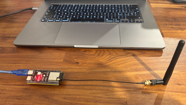
Although [Thomas] really likes the Raspberry Pi Pico 2 and the RP2350 MCU, he absolutely, totally, really doesn’t like the micro-USB connector on it. Hence he jumped on the opportunity to source a Pico 2 clone board with the same MCU but with a USB-C connector from AliExpress. After receiving the new board, he set about comparing the two to see whether the clone board was worth it after all. In the accompanying video you can get even more details on why you should avoid this particular clone board.
In the video the respective components of both boards are analyzed and compared to see how they stack up. The worst issues with the clone Pico 2 board are an improper USB trace impedance at 130 Ω with also a cut ground plane below it that won’t do signal integrity any favors.
There is also an issue with the buck converter routing for the RP2350 with an unconnected pin (VREG_FB) despite the recommended layout in the RP2350 datasheet. Power supply issues continue with the used LN3440 DC-DC converter which can source 800 mA instead of the 1A of the Pico 2 version and performed rather poorly during load tests, with one board dying at 800 mA load.
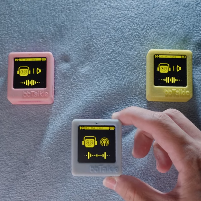
Walkie-talkies are great fun, and [RealCorebb]’s bbTalkie project takes the concept a step further by adding some extremely cool features to make a highly refined, self-contained ESP32-based communicator. bbTalkie completely does away with a push-to-talk button by implementing robust voice detection that works reliably even in noisy environments. It was all designed with cycling in mind, so hands-free operation that stands up to noise is a big plus.
Hands-free, wireless, self-contained digital walkie-talkies that can connect in a group. What’s not to like?
The core of communication is done over ESP-NOW, which is Espressif’s own protocol for direct device-to-device broadcasting. This removes the need to involve any sort of external service like SIM cards or internet access to transmit voice. Performance is best with an external antenna, naturally, but ESP-NOW doesn’t actually require anything other than the existing on-board hardware.
Because volume-based automatic triggers are highly susceptible to noise, voice detection is done with the help of VADNet, a neural network-based model implemented locally on the device. This system can reliably detect human speech, even in noisy environments. This lets bbTalkie switch between transmit and listen modes automatically and hands-free, without false triggers.
Even when doing all that, there’s still spare capability to play with. Further to the goal of making bbTalkie useful for cyclists in a group, [RealCorebb] added a system that can recognize specific voice commands (like “turn left” for example, or “wait for me!”) which trigger synchronized animations to play on the displays of all connected units. There’s even some experimental support for controlling a camera over Bluetooth, though currently it only supports hardware from Sony.
Watch a tour of it in the video below (Chinese language, English captions available). The OLED screens and animations are adorable, and are great visual feedback of what the unit is doing at any given moment.
Home automation with high usefulness and low annoyance tends to rely on reliable person sensing, and [francescopace]’s ESPectre shows one way to do that cheaply and easily by leveraging hardware that’s already present on a common dev board.
ESPectre is an ESP32-based open source motion detector that detects movement without any cameras or microphones. It works similarly to millimeter-wave (mmWave) radar motion detectors in the sense that when a person moves, wireless signals are altered slightly as a result. ESPectre can detect this disturbance by watching and analyzing the Wi-Fi channel state information (CSI) and doing some very smart math and filtering. It’s cheap, easy to deploy and use, and even integrates with Home Assistant.
Combining a sensor like this with something else like a passive infrared (PIR) motion sensor is one way to get really robust results. But keep in mind that PIR only senses what it can see, whereas ESPectre works on WiFi, which can penetrate walls.
Since ESPectre supports low-cost ESP32 variants and is so simple to get up and running, it might be worth your time to give it a trial run. There’s even a browser-based ghost-dodging game [francescopace] put online that uses an ESPectre board plugged in over USB, which seems like a fun way to get a feel for what it can do.
Normally, if you want to blast out samples to a DAC in a hurry, you’d rely on an FPGA, what with their penchant for doing things very quicky and in parallel. However, [Anabit] figured out a way to do the same thing with a microcontroller, thanks to the magic of the Raspberry Pi Pico 2.
The design in question is referred to as the PiWave 150 MS/s Bipolar DAC, and as the name suggests, it’s capable of delivering a full 150 million samples per second with 10, 12, or 14 bits of resolution. Achieving that with a microcontroller would normally be pretty difficult. In regular linear operation, it’s hard to clock bits out to GPIO pins at that sort of speed. However, the Raspberry Pi Pico 2 serves as a special case in this regard, thanks to its Programmable I/O (PIO) subsystem. It’s a state machine, able to be programmed to handle certain tasks entirely independently from the microcontroller’s main core itself, and can do simple parallel tasks very quickly. Since it can grab data from RAM and truck it out to a bank of GPIO pins in a single clock cycle, it’s perfect for trucking out data to a DAC in parallel at great speed. The Pi Pico 2’s clock rate tops out at 150 MHz, which delivers the impressive 150 MS/s sample rate.
The explainer video is a great primer on how this commodity microcontroller is set up to perform this feat in detail. If you’re trying for accuracy over speed, we’ve explored solutions for that as well. Video after the break.