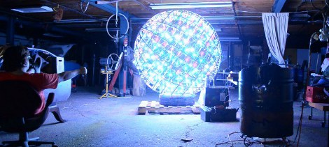
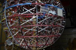
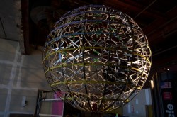
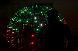
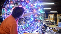
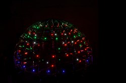
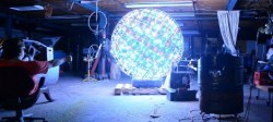
About half a year ago [John] over at Frank’s Kitchens came to me with an idea for a giant lighting project. He had this 6ft diameter aluminum frame globe rescued from the Philadelphia Theater Company and wanted it to be an interactive display of sorts. After a few discussions we got together and somehow managed to order 800 3 watt LEDs in red, green, blue, and white. We had a system that worked great on paper, and managed to get it built by Valentines day for a big show. It failed miserably and hardly even illuminated the LEDs. I, naturally, took this far too personally and set out for a complete redesign, looking in the direction of digitally addressable LED strips.
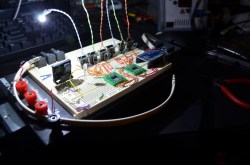
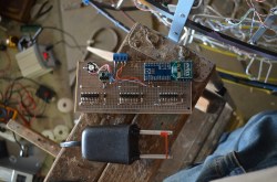
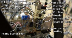
In addition to building a crazy turbo charged LED array I also spent a lot (a whole lot) of time coding a nice clean fully functioning RGB LED strip controller using an Arduino Pro Mini (5V 16 MHz), the MSGEQ7 audio frequency multiplexer (PDF) , and an IR remote. I plan on using this for other projects so the code can be easily reconfigured to use many different LED strips and a whole slew of IR remotes.
The schematic of the globe is here. The top half of that schematic be catered to other projects using a variety of pre-built LED strips. The pastebin with code is here, fastSPI_LED and IRRemote here and here. Some code jockeying was required to get IRRemote.h and FastSPI_LED to play nicely together, so check the code comments.
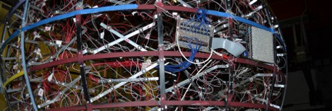
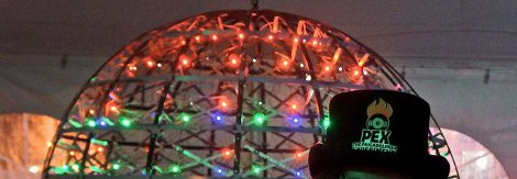
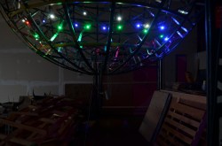
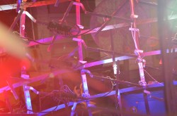
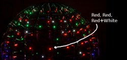
At the start of the build I had a huge frame with red, green, blue, and white LEDs arranged in pixels on aluminum brackets. I had to strip out a ton of over sized wire, and two completely destroyed Peggy2 boards. I kept getting asked if the Peggy 2 system could just be resurrected; aside from the coding nightmare that Peggy presents (at least for a coder of my level). The original goal was to individually power every single LED (720 in total), and appropriately fade them with an individual PWM signal. This is impossible with Peggy since it relies on a row-at-a-time enumeration of an array. Keep in mind the system is great and works amazingly well for lower power applications. We had strapped high power drivers to each column and a high current MOSFET to each row. Below was a panicked “short every control pin of every driver to just light it up” version, and yet it could only put out that pithy amount of light. Everything had to go. Even my top hat.
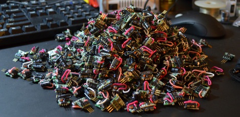
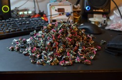
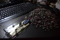
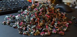
Since the complete overhaul was now my project my budget and my money I had to keep the LED drivers under a dollar each. Well under a dollar each. Enter: China. I managed to source some crazy 12V AC drivers that were meant to replace track lighting. The boards use the MC34063 switching regulator (PDF) in some configuration that wasn’t shown on the data sheet. Lots of pencil sketched circuits later I had a reverse engineered schematic and no clue as to what it was trying to accomplish. It took some google-fu but I managed to find a current driver schematic for the IC, primarily due to my inability to spell. The schematic looks just like my drawing and has a nice simple way to pump a slow speed PWM signal into the chip, Pin 5. Cool, this is so simple: just peel up Pin 5, replace the input posts with a 3 pin connector and wire the middle pin to the chip.

It worked fantastically with a PWM signal. Now I just had to do that… 800… times.
To provide that PWM signal I needed something cheap, available, simple, and capable. I tested a few methods of driving the driver, and settled on the WS2801. This chip was easy to find cheaply, and handled all of the serial signal transmission and boosting through serial in and serial out pins. The big issue is that this chip is meant to only control RGB, not RGBW. This actually ended up being a massive problem, EVERYTHING is catered to RGB arrays, and here I was with a giant (expensive) RGBW setup. Since each WS2801 controls three LEDs, I decided to tack the white LEDs onto every 4th driver in line. I haven’t gotten around to making my code work with this scheme yet so the output looks kind of funky in the videos.
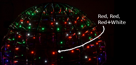
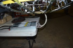
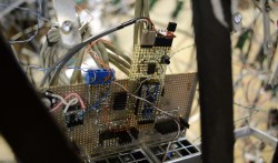
Each PCB when running can draw up to 2A of current (on the 12V line). In order to supply 60 of these boards I managed to find a couple hot swappable server power supplies. Actually 6 of them, each providing a whopping 52 Amps Max. I also bought the controller board they plug into and pried the connectors off, mounting them to perf boards. I used Ethernet wire pretty much exclusively for the entire project, it melts and shorts and doesn’t like to bend more than a few times. It was awful. The wire was cheap though, and I am still debating if the few hundred dollars to design this thing with connectors would have been worth the time savings considering I hadn’t tested it with connectors.
![]()
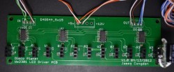
At any rate this was a pretty fun project. I still have to sort out a few buggy LED drivers, and glue the driver boards to the PCBs (they’ll unplug while transporting). I plan on making a few more of these controller circuits since I have to test code two states away from the shop, also I can put them in other stuff. Sound reactive top hat? Maybe I can inspire [Caleb] to do a bit more with his RGBW globe. Here is a break-down of the controller parts:
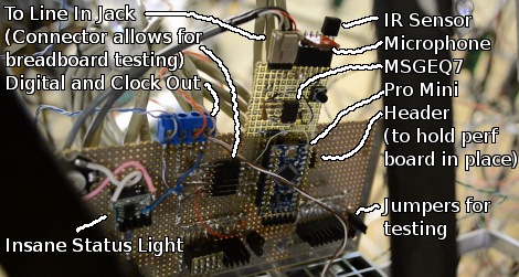
Below is the crappy video from the day I finally got the driver circuit installed, under that is one of the first “woohoo my code works” video. I’d have a better video to show off the circuit and modes and IR but I had to use my breadboard parts in the globe! I ran over my spare microphone breakout board with my chair and totally crushed the poor little guy.
[youtube=https://www.youtube.com/watch?v=v-bGqV5o_bE&w=470]
[youtube=https://www.youtube.com/watch?v=nLmlFjeQ4bs&w=470]
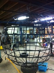
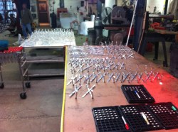
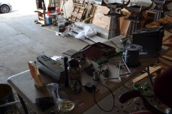
Also just to annoy people trying to scroll down to the comments section, here is a massive gallery of photos for a massive project. Check out the comments for more info. Some decent computer background fodder in there as well.





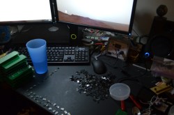
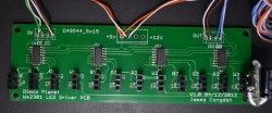
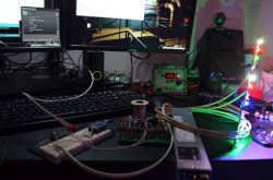
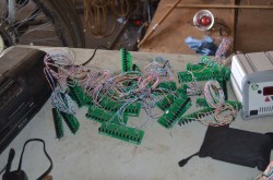
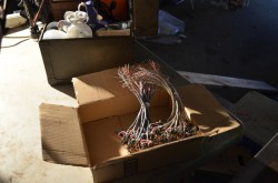
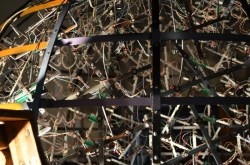
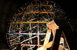
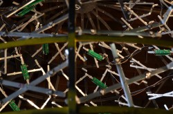






Very impressive and blindingly bright,
well done! :)
Cool! I wouldn’t have much of a use for it because it’s so HUGE, but that could make for a nice profit if sold to the right people.
Also, what’s up with the muffler just hanging around?
Frank’s makes a lot of pedal powered bike-like vehicles, and I think that crazy muffler is some attempt to motorize one. I’ts been kicking about as decoration since I’ve been hanging out there. I know we hung it in a Frank’s Kitchens DJ tent once.
Hey Jesse,
Can you share where you sourced the LED driver boards from? I have a related project (much smaller scale) and I’m interested to see how much it would cost to buy those instead of fabbing everything myself. I need about 64, not 800. ;)
Nice project.
I can’t get anything past you guys. I completely forget the specifics of how we acquired all of these LEDs. I ended up narrowing down the types of high power LED to three companies, luxeon… and… two others I forget. I chose the cheap one and found all of their info. A friend of ours who works in the flashlight biz got in touch with them and they coordinated the order as a sample. I have no idea how they did that its magic to me. We had to get a massive quantity though they wouldn’t take our order of 720.
Thanks, I was actually asking about the driver boards, tho, not the LEDs.
OH! E-bay, I don’t want to link directly cause things expire. The title is: “20x Power Driver 1x 3 W Watt LED Light Lamp 12V MR16”. Any variation of that text should get you what you are looking for. Keep in mind the circuits vary and what was pictured in the auction was not what I ended up getting in the mail. I made 4 or so orders of these things and apart from wire color they were consistently not in the configuration pictured! Luckily they were all the same wrong configuration.
Perfect, thanks!
I did a short video on how to mod such driver boards. You can find a link to dx.com (SKU 13553) in the video description.
http://www.youtube.com/watch?v=sohPA29wnFo
Nice re-use of the globe but that would of be so much easier and tidier if you had designed a PCB with the drivers on and routed it nicely rather than as a rats nest of cat 5. Those drivers are designed to take in 12V AC so the 4 diodes and large cap is not strictly necessary (small cap would work). Those boards will have next to no filtering so that thing will be pumping out noise on the RF frequencies. We recently made the CAT 5 mistake also : never wire cat 5 direct to a board. It breaks _instantly_
Hoo boy don’t I know it. I have a design swimming around in my head now that I am so familiar with the driver circuit and the LEDs. In the future I may make a board that has a 2801, three drivers and an RGB 3W LED instead of individuals spread out like they are in this thing. With that pixel density the globe could do blinding video. I simply do not have the money, and would have to put it on an aluminum PCB to dissipate heat (maybe I could get star boards but the drivers get to like 120 degrees as well). The insane mess of cable adds to the ascetic I kind of like it. I also had no choice in the matter, I didn’t have the luxury of throwing out 100 bad designs!
Also if you’d like to go through and remove 2880 diodes and jumper 1440 of them, be my guest! The cap isn’t entirely unnecessary, it helps the power supplies when I do operations like flashing the entire strip 100% at once… At least that’s what I tell myself.
If you must put cat5 to board, hot glue helps. Lick your finger and push it down all around the wires to get a good bond.
Cute. I still don’t understand why all these lighting projects are always built with custom controllers instead of a dmx interface through :(
I would think that since it always gets brought up in the comments people would start taking advantage of it eventually. It would simplify a ton of the effort in making a project like this do cool things.
I’m sure the big led stars installation in the time warner building in ny (during xmas) is all dmx.
Still a fun project though.
DMX (or DMX512) is an excellent idea! This is the communications used to drive the robotic lighting and motos in night clubs and stage shows.
If you implement a DMX512 input port to your globe, your customer would be able to control the globe with their hardware and software.
Fantastic job! Your technique for the LED drivers was really interesting. And the MSGEQ7 is definitely a chip I intend to play around with in the future.
I took a different route for driving high power LEDs: In my case, I was using the TLC5940 from TI: 16 channels of constant current output at 120mA per channel, with input data fed via SPI. They can be finicky, but they are fantastic for 3W LEDs (I use cheap RGB LEDs from DealExtreme); you just tie a bunch of the CC outputs together in parallel.
I believe these chips are designed for driving dot-matrix jumbotrons because they have an EEPROM in them that lets you perform grayscale correction.
The TLC5940 does look cool, I played around with some of the ton-o-PWM shift registers at the very beginning of the overhaul but I wasn’t too excited at the prospect of running a single serial line in a giant spiral around the entire planet. just SD and CK lines were enough to have me pulling my hair out! Can you get more than 64 levels of brightness by activating the PWMs tied together in a sequence?
Yeah you definitely cannot chain these guys very much. A friend of mine discovered that after about 5 of them, the data lines are severely degraded. I solve the problem by having an Atmega control a bunch of them via SPI. Each Atmega is then connected via an RS-485 network, which lends itself nicely to fast communication over long lines. A “master” (e.g. computer) then drives the network, instructing each module what to do with a simple serial protocol.
Erm, I didn’t quite understand what you mean by more than 64 levels of brightness? The TLC5940 is 12-bit, so each of the 16 channels has 4096 levels of brightness. You feed in 12*16=192 bits of data per chip per “frame”. If you tie the serial output of one chip into the serial input of the next, then you’d just feed in 2*192, etc. etc.
TI makes a few variations of this chip that have fewer channels and/or lower current output.
Feel free to learn or steal from my project as much as you’d like: http://jwcxz.com/projects/acris . It’ll also probably be making an appearance at World Maker Faire NY in some form or another (I’m currently working on trying to come up with a new, more interesting lighting display). I think scalable displays are a really cool challenge.
Oh! I totally glanced at the data sheet and misunderstood. That’s really cool, here I am thinking my calculations are ridiculously cycle heavy with 255 levels.
Wow, looks like they got it from Area 51!
Sort of offtop, not sure to whom it may concern:
I’m receiving new articles from hackaday.com via RSS. This message is slightly different from all previous: it has full links on all the pictures and HTML code in the end like:
” data-medium-file=”http://hackaday.com/wp-content/uploads/2012/09/discoplanetschematic.png?w=300″ data-large-file=”http://hackaday.com/wp-content/uploads/2012/09/discoplanetschematic.png?w=450″ width=”128″ height=”77″ src=”http://hackaday.com/wp-content/uploads/2012/09/discoplanetschematic.png?w=128&h=77″ class=”attachment-thumbnail” alt=”00_DiscoPlanetSchematic” title=”00_DiscoPlanetSchematic” />
Is there a way to cut this sort of things in RSS (maybe you can send only article’s headers)?
Thanks in advance.
GO PEX KREW!!! <3 the camp formerly known as imagenode…
Hi,
I wanted to let you know your Arduino project has been added to a list of 20 Arduino projects of 2012 published on Nudatech’s blog ( http://www.nudatech.com/blog/20-arduino-projects-of-2012/ ).
Please let me know if there’s any mistake in the short note I wrote about it and if the link I chose for it is the right one.
Obviously sharing the list on social networks, blogs and forums is also appreciated :-)
Regards
Very cool Sphere but you need some space for it. Should be nice to see a dance floor equipped with your device ;)
Nice one.
I made a project ( much smaller -_- ) too with msgeq7 + arduino:
https://www.youtube.com/watch?v=3aTjIN7bjg0