After making your first PCB, you’re immediately faced with your next challenge – drilling the holes. It’s a doable task with a small drill press, but a lot of makers already have a small CNC mill or router, but how to make that work the first time? [Alessio] has you covered with a technique that uses a CNC-mounted webcam and some linear algebra for perfect through-holes the first time and every time.
A few months ago we saw [Alessio]’s work with transform matrices and PCB drills. The reasoning behind this technique is if a PCB isn’t exactly aligned to a CNC mill’s axes, or if the scaling for a toner transfer board is a bit off, automating the drilling process will only end in pain, with holes going through traces and a whole host of other nasty things. The application of linear algebra gets around this problem – taking a measurement off of two or three known locations, it’s easy to program a CNC machine to drill exactly where it’s supposed to.
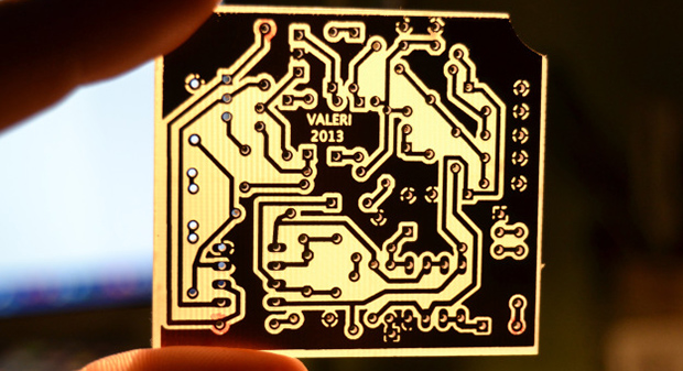
[Alessio]’s new project takes the same mathematical techniques and applies them to a very sleek application that uses a drill-mounted webcam. After taping his homebrew PCB down to the mill, [Alessio] simply marks off a few known points, imports the drill file, and lets a computer calculate where to drill the holes. The results are remarkable – with a soldermask and silkscreen equipment, these handmade boards can be just as good as professionally manufactured boards,
There are Windows and OS X binaries for [Alessio]’s tool available on his page, with a video demo available below.
[youtube=http://www.youtube.com/watch?v=tzI445XsPDs&w=580]


That is absolutely fantastic!
I have to wonder if this codebase might also prove somewhat useful to those of us who dream of homemade pick’n’place machines?
I imagine so. This is similar to what well designed electronics do with fiducials: http://www.ladyada.net/library/pcb/fiducials.html
Nice hack! but “As good as professionally manufactured boards” is an absurd overstatement. Not that this boards don’t look fantastic for most hobby projects, and even for some very small commercial use. But the quality is not comparable to even the lowest quality standard in the “professionally manufactured” league, not even with a solder mask and silkscreen.
That’s true. But then again, professional usually means “paid for”. And this board appears to have better drilled hols then some of the “paid for” boards people have been posting pictures of when comparing PCB houses.
More to the point… Let’s be honest, is not a real board first drilled? Then the holes plated? Then masked? Then etched? Then cut? So the real alignment would be the mask onto a previously drilled out board.
In the end, I really like this solution. It proves once again that software (usually regarded by business types as an after thought) is a very powerful tool. Using the same hardware, software can “fix the inherent problems”. It can “stabilize a plain’s flight”. It can “prevent train accidents”. It can “drive a car”.
While I mostly agree you need to remember that comparisons between board houses typically push the boundaries for size, you might see a board with annular run-out but it’s not fair to compare a 5mil commercial drill dot to a 20mil hobbyist one. It’s all a perspective of scale usually and paying attention to the sizes noted is crucial in realizing which has more accuracy.
> But then again, professional usually means “paid for”.
Don’t kid yourself…this board was “paid for” also. The parts alone must be ~$200 plus the time to build it and write the software, learn EMC etc. That’s easily a $1000 investment. $1000 can buy you a lot of boards…just sayin.
I don’t think that hardware is only usefull for drilling and making PCBs. Also 1000$ you will get you approx. 10 boards, if you want them within a few hours like you do with home-made PCBs.
So you still have to locate all of the holes. How about introducing some object recognition through the camera and have software determine all of the hole locations?
Yeah, that’s my impression too. From the video. But Brian’s comments were: “…simply marks off a few known points, imports the drill file, and lets a computer calculate where to drill the holes…”. If Brian is right, the software is cool. If you are right, I concur, the software needs improving. What would really be cool wold be if the software “guessed” where the holes were, then centered the hole based on the image of the pad. Which, I think, is what you are suggesting.
Video has his manually do one hole, then a text says ‘do tis for the remaining holes’ and skips to showing the results of that hours work..
Really, this doesn’t seem much of an advantage to doing it by hand.
When he says “remaining points” he means the other two holes the software needs.
“Now I can pick up three points and locate the relative pads center trough the camera. It is common sense to not choose points that lay on a straight line. Of course the farther the points are, the better the result could be.”
You have to locate *some* of the holes, so that it can scale and rotate the matrix. However, it looks like he only located two holes on the left side of the board in the above photo.
Locating just TWO holes is sufficient to get rotation and scaling matrix.
Three points would compensate for aspect ratio distortion, uncommon but not impossible with a hobby grade CNC.
I get skewed output from my laser printer so I use a similar 3 hole method to locate holes.
Dam you [Alessio]! :-) I have done this same, but didn’t have time to publish it. BTW: EMC2 has pretty simple python interface, so I have click picture to move CNC machine interface. And you can also read coordinates with python, so no manual typing. (did a web service for that)
if you have a CNC, why not drill the board first and then align the image to the drills.
I used to do that with toner transfer, even though i did not drill the holes with a cnc, just manually.
The advantage of drilling before you place the image and etch is that the holes look much nicer.