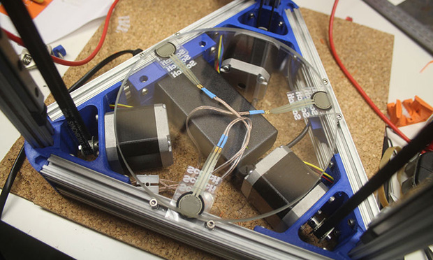
[Johann] over on the RepRap wiki has an ingenious solution for making sure a borosilicate glass bed is completely level before printing anything on his Kossel printer: take three force sensitive resistors, put them under the build platform, and wire them in parallel, and connect them to a thermistor input on an electronics board. The calibration is simply a bit of code in the Marlin firmware that touches the nozzle to the bed until the thermistor input maxes out. When it does, the firmware knows the print head has zeroed out and can calculate the precise position and tilt of the bed.
Great, huh? A solution to bed leveling that doesn’t require a Z-probe, uses minimal (and cheap) hardware, and can be retrofitted into just about any existing printer. There’s a problem, though: these force sensitive resistors are only good to 70° C, making the whole setup unusable for anything with a heated bed. Your challenge: figure out a way to use this trick with a heated bed.
The force sensitive resistors used – here’s a link provided by [Johann] – have a maximum operating temperature of 70° C, while the bed temperature when printing with ABS is around 130° C. The FSRs are sensitive to temperature, as well, making this a very interesting problem.
Anyone with any ideas is welcome to comment here, on the RepRap forums, the IRC, or anywhere else. One idea includes putting an FSR in the x carriage, but we’re thinking some sort of specialized heat sink underneath the bed and on top of the FSRs would be a better solution.
Video of the auto bed leveling trick in action below.


Perhaps put a small chunk of aerogel in between the bed and the FSR?
I doubt that aerogel would be stiff enough to provide the support that you would want. Possibly a ceramic insulator?
Thopter and Alex are right on. No need for some of the fancy solutions suggested, or changing the design to, e.g., capacitive sensors as suggested in one of the comments. A bit of insulation will fix this problem. Don’t have the FSR’s in direct contact with the heated bed, and if possible get a bit of air flow between the bed and the FSR’s to reduce conductive heat transfer. Seems like the ideal structure might be perforated cylinders the same diameter as the FSR’s. Sit the cylinders on top of the FSR’s, and sit the bed on top of the cylinders.
Note that Thopter, presumably jokingly but it really is a good design if you want to avoid custom parts, suggests Coke caps (I assume aluminum, not plastic, ones) in a comment below. Something like that is almost ideal — the very thin walls make for poor heat transfer via conduction (which you don’t want — that will heat up the FSR’s), but good cooling via convection (air flow), and the shape allows such thin walls to be strong. It’s actually hard to think of a much better solution that doesn’t require machining or hunting down special parts.
Finally, note that FSR’s which can take high heat are available, so if you’re willing to spend the money you can just ignore this issue completely. See https://www.tekscan.com/products-solutions/force-sensors/ht201. However, when regular FSR’s can be found for under $10, and they want over $40, that’s hard to stomach just on principle.
They can probably handle the heat. 70° C is only a conservative estimate. Going by the actual datasheet, high temperatures merely change the resistance, making it less accurate. Since the sensor is basically only used as a maxed out contact switch, it shouldn’t matter much.
http://media.digikey.com/pdf/Data%20Sheets/Interlink%20Electronics.PDF/FSR400_Series.pdf
Also, the operating temperature is different from the storage temperature. Letting the plate cool down before calibrating should restore accuracy.
The problem could be bypassed entirely by using capacative sensors instead. Replace the force sensors with thin metal, and measure the capacitance between them and the print nozzle. Keep moving the head closer until the capacitance stays constant, which should indicate contact with the plate.
That would require ramming the nozzle into the bed hard enough that it would stop moving for a significant amount of time. This is gentler, since the FSRs are triggered almost instantly.
So, just thermally isolating the hot bed parallel to this wouldn’t work?
I imagine pieces of diabond might do the trick. The bottom side may be anodized black to radiate away the conducted heat. The material can also be made a bit longer so it protrudes from underneath and act as a heat sink (cut a groove on the top side to disable heat diffusion).
Could always use a ceramic washer http://us.misumi-ec.com/vona2/detail/110300236720/
I’m with Willie. A 1/8″ mdf sheet glued to 1/2″ high-density styrofoam (XPS) insulation should do the trick. If that’s not enough, laminate some aluminum foil on top of the MDF to act as a heat reflector.
Just a couple layers of kapton tape maybe an aluminum shim as a heatsink on the bottom side.
couldn’t you just level the bed then preheat?
I read the summary, but I don’t understand how this actually works. Can anyone ELI5?
So the number and location of the sensors is unimportant – just the ability to sense when the print platform is pressed down (by the extruder). It could also be done by sensing the reactive force on the head as it’s pressed into the surface (but that requires a bit more care given it can move around).
Then, knowing where you are moving the head, you move it down over at least three different locations to deliberately impact the bed (normally a big no-no). When the force on the bed hits a defined threshold (i.e. you sense that the extruder has hit the bed) you mark the location. Repeat it for the other two locations and, voila, assuming a flat top to the bed you know the plane that the bed is sitting on (using a bit a maths).
Ideally the three locations should be as far apart as possible to reduce inaccuracy but you’d also need to ensure you sense at the same pressure point for the three locations (which, in this setup, means the three spots where the sensors are).
Drink 3 20oz Cokes (not at once) and save the caps to put between the bed and the FSR.
Wahahahaha. I like that a) this would probably work (a Coke cap is actually a great shape because it will support the weight with minimal heat transfer since it is hollow), and b) OP was kind enough to warn against consuming too much caffeine or sugar at once.
How about mounting a single FSR on the head, for example between the extruder assembly and it’s mounting bracket? The bracket looks like it’s 3D printed, so it can’t be very hot there or else the plastic would melt. When the head pushes against the build plate, the build plate “pushes back” with equal force and would trigger the force sensor.
I agree.
And you’re only using one sensor rather than three, clever idea! Very elegant solution.
Perhaps you can ditch the FSR altogether and use a Wheatstone bridge strain gauge setup. It’s exactly the same technique except the gauges work at higher temperatures.
I was wondering whether you could also use QTC Pills: http://www.technobotsonline.com/qtc-pill.html – they’re rated to 120c. I’ve not read the datasheet yet though. They’re cheap enough though.
very easy to make it work with a heated bed. a second piece of glass the same size that has a couple mm gap from the first one. easily done with either a high temp silicone ring or other meterial and some glue. Glass is a bad heat conductor and the air gap will be enough insulation.
Technically, you don’t need three sensors, you only need two, and you can place them on the ends of levers that spread out like a V shape from a mutual pivot so they’re never in contact with the actual heated bed.
The pivot is a known point, so all you have to do is figure out where the other two ends are going, and you got yourself a plane.
I don’t understand the advantage of having three sensors on the bed when you could do the same having one on the probe…
Three FSRs in this configuration, causes a reading of the force applied to be nearly the same no matter where probe touches.
There are mathematical equations for calculating tilt and direction of tilt from just 3 points. Not sure why the process he uses gets like 30 points on the bed before determining…
I have a glass bed on my printer and have noticed that as plastic is applied to the first layer, the line width and height varies slightly in different bed locations. I believe this occurs because the glass build plate surface is not flat within the tolerances required.
By sampling lots of points, they can find the high and low spots and compensate to get the first layer of plastic to adhere well and extrude lines of consistent width. This compensation is probably more important when printing with really thin layers or tricky materials.
The large number of points is to compensate for the slight dish shape present in the motion of delta bots. Its a quick way fudge the calibration allowing the edges of the head movement to be flat relative to bed.
The bed needs to be hot during the probing due to expansion, the surface map would be different on the bed cold than the bed hot. I believe 3 are used as it defines a plane. I was thinking of putting them under the insulating plate underneath the heated bed.
inline peltier
You can’t put the sensor in the head because you want everything up there to be screwed tight (Especially on a Cartesian bot).
I have my bed on springs so that a hot end crash doesn’t crack my glass or start bending my rods or worse, saved me 3 times so far. I wonder if there’s a way to make this work with that setup and a heatbed that goes to 130C (without adding weight to the Y carriage).
I still want a way to auto level a Cartesian bed without adding significant weight to the carriage or requiring Z to move up/down on every X/Y move. And I wonder how this could be achieved with a cantilever bed.
I thought about massively geared up $5 steppers with drivers raising/lowering the ends of the Y rods. But that would probably cause some binding of the Y carriage.
My heated bed has cork under it, according to the ir thermometer it gets to 60c with the bed running at 120
How thick is the cork? Also, do you use FSRs underneath it? I’m curious if there’s too much flex in cork to have it be inbetween the FSRs and your bed.
Piezoelectric crystals are a perfect replacement can work in high temperatures and are easy to get (they are in electrical lighters)the problem is they need some kind of a base in order not to break the glass, and a way to wire them.
I would go for piezo as well…
You can find metal discs with piezo on them inside cheap speakers or buzzers.
Would it not be possible to measure the power used by the Z-axis motor(s) to determine how much force it is applying, and stop when the amps spike? Say, with an ammeter?
Ditch the resistors. Measure current and voltage in the X and Z axis motors while the head is doing tiny and slow low power circles as the Y axis gently lowers towards the bed. When your power consumption goes from what you get in free movement to the load from the head contacting the print bed you have your contact point and you can back off and measure another spot.
With the resistors out of the way, the bed can be heated as much as you want.
I’ve seen this used with milling machines to measure ceramic blocks about to be milled with diamond burs. The touch tests barely scratch the block and are as accurate as your cutter is. A smooth hot end touching the bed will be a lot gentler than a cutting bur, so nothing should get damaged.
I doubt that current in stepper’s coils increases when stepper is being stopped- steppers are already being driven by constant-current motor drivers (on majority of RepRaps).
I have also tried piezo crystals- the problem with that approach is- in order to filter out motor noise and vibrations, you need a fast and quite hard “tap”. I also tried FSR’s between hotend(s) and carriage- it did not prove to be reliable. When FSR’s are squeezed, their resistance drops gradually (and small surface imperfections make it impossible to operate it in “slightly” squeezed scenario). Hinged carriage + microswitch has given me better results (but then there’s a problem with linear rods bending in the middle). I’m not building a delta, so your mileage may vary.
What about placing a piece of heat reflective film on top of the FSR?
Some are rated to take up to 500F of radiant heat,
but how do you wire it in? I’m new at this