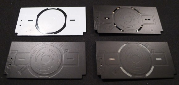
The Hackaday community offline password keeper is slowly coming together. A few days ago we received the top PCB for Olivier’s design (shown above). If you look at the picture below, you may see the problem we discovered when opening our package: the soldermask was the wrong color! Given the board is meant to be placed behind a tinted acrylic panel, this was quite a problem…
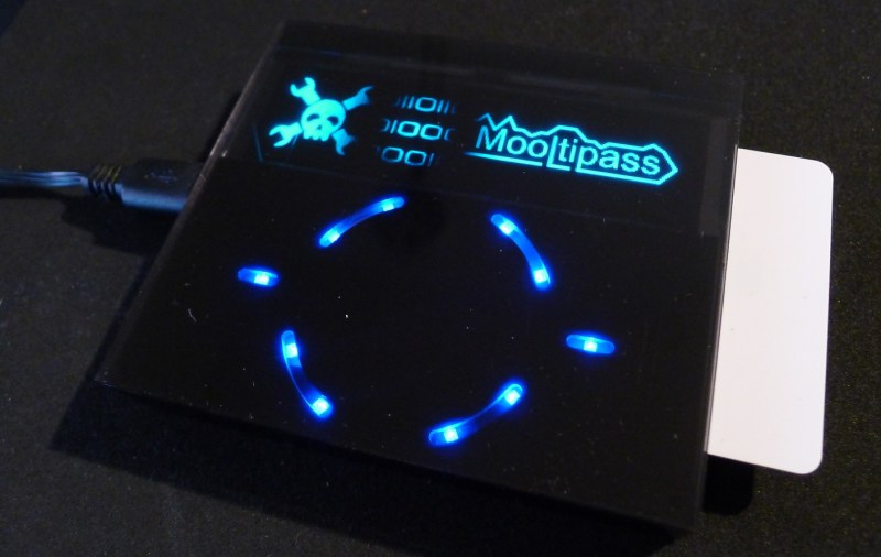
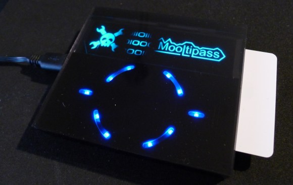
After using some spray paint, we managed to get to the point shown in the bottom left of the picture. The next task was to find the best way to illuminate the input interface with reverse mount LEDs. Using a CNC mill we machined openings (top right PCB) but also removed some epoxy on both PCB’s sides, thinking it would provide a better light diffusion. We then wrote part of the Mooltipass PWM code and took these pictures:
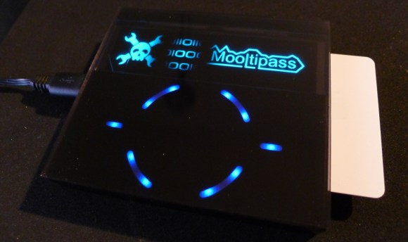 Using the FR4 to diffuse the light
We hope you agree that the ‘FR4 version’ looks better. The other version, which has the cut openings, illuminates unevenly because the smartcard isn’t under all of the LEDs. This raises several questions that we hope our dear Hackaday readers can answer:
- Can this kind of machining be done in standard PCB fabs?
- Instead of leaving the bare FR4 on top, should we cover it with white soldermask?
- Instead of leaving the bare FR4 on top, should we cover it with white silkscreen?
Keep in mind that we would only need to machine one PCB’s side.
Another concern is the top panel. As previously mentioned we’re currently using a tinted acrylic panel, which may not be the best solution to prevent scratches. We’re thinking to use glass in the future (corning gorilla glass?) so we may also hide everything around the display’s active area. Do you guys have any experience with this? Would it be expensive in relatively small quantities?
As you can see, we still need to find the best compromises and we hope you can help us. Please post a quick message in the comment section below or contact the team in the official Mooltipass Google Group.



If the slots you need are not plated, almost all PCB vendors can make them at little or no cost, as it is just a slightly more complex program for routing the PCB from the panel.
White soldermask or silkscreen is fine. In general, silkscreen is already white, so you won’t have to pay a surcharge which is likely if you want white soldermask. The drawback is that silkscreen is typically still *actually* silk-screened in many shops, meaning it has lower resolution than the soldermask which these days is almost universally photo-imaged (either dry film or LPI/Liquid Photo-Imageable). For your application, it doesn’t seem like the resolution would matter much one way or another, and white silkscreen would be cheaper.
You mentioned being concerned about scratches. What about including a number of precut, clear plastic aggressive guards like some people put on their cell phones? A few bits of protective plastic has to be less expensive than Gorilla Glass tm.
Aggressive should be adhesive
Comparison between glass, acrylic and polycarbonate.
suggests acrylic or polycarbonate(stronger but 35% more expensive) with a scratch resistant film (Lexam MR10) is best solution.
http://www.northalabamaglass.com/acrylics.htm
http://www.coloradoplastics.com/blog-0/bid/42625/Polycarbonate-Lexan-vs-Acrylic-Lucite
http://blog.theplasticpeople.co.uk/2012/06/01/how-are-polycarbonate-acrylic-different/
thanks!
Simply make the PCB without solder mask on the backside where the illumination should show through, then mount the leds behind there. You still have a lot of point illumination in the sample, more FR4 between the LED and face should diffuse better. The other option to illumination is to edge light some acrylic pieces that fit into milled out slots. Take the milled design, then put leds around the edge of the slot, not visible through the slot, and use acrylic as a light guide. If you sand or blast the exposed acrylic in the slots, it will give a diffuse frosted illumination.
Unfortunately the reverse mount LEDs need a slot of some sort. Changing the LED type would also add some depth to the case. We also thought of using edge lighting but were skeptical about how well the light could be diffused…
http://www.dialight.com/Assets%5CBrochures_And_Catalogs%5CIndication%5CSMT_selector_guide.pdf
They have right angle SMT LED (page 9) which are good for edge lighting. They have a viewing angle of 135 to 140 degrees. I wonder if the light coming off the side is enough for this.
There are also reverse mount LED (page 9) that only require drilling a hole and the height is 1.1mm (less than thickness of PCB).
… um how about a solder-mask cut out where you want light to show through? They’re usually simple to specify in the layout program.
I think we’ll opt for this solution + some light milling on the other PCB side
Can anyone tell me what i would use for a google string to learn more about the 3 interleaved sawtooth sections that im assuming make for a sort of touch sensitive knob?
“capacitive touch wheel electrode design” is a good start.
Here’s one way to draw them: http://bryanduxbury.com/2013/12/05/designing-a-capacitive-touch-wheel-in-openscad-and-eagle/
Tempered glass is strong and will never scratch. The minimum thickness for a credit card size 3 3/8″ × 2 1/8″ (which is relatively small) in most of factories is around 3/16″. The price from onedayglass.com for “Tinted, Pencil Polished edge-work” in Qt. of 100 is $16.50/piece.
https://secure.onedayglass.com/ordernew.php
Is there some kind of sign up list to buy one of these when the become available? M
Hey Matt,
You can subscribe to the google group to stay informed :)