A Spark Gap Transmitter, Characterized

When we think of a spark gap radio transmitter, most of us immediately imagine an early twentieth century ship’s radio room or similar. Most of us know these transmitters as the first radio systems, and from there we’ll probably also know that they were phased out when better circuits arrived, because of their wide bandwidth. So it’s rare in 2024 to find anyone characterizing a spark gap transmitter, as [Baltic Lab] has.

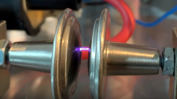
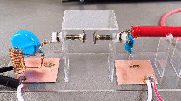
The circuit is simple enough, a high voltage passes through an RC network to a spark gap, the other side of which is a tuned circuit. The RC network and the spark gap form a simple low frequency relaxation oscillator, with the C being charged until the spark gap triggers, forcing the subsequent discharge of the capacitor and causing the spark to extinguish and the cycle to repeat. The resulting chain of high voltage pulses repeatedly energizes the tuned circuit, with each pulse causing a damped oscillation at its resonant frequency. The resulting RF signal is a crude AM tone which can be received fairly simply.

The mathematics behind it all is pretty interesting, revealing both the cause of the bandwidth spread in the low Q factor of the tuned circuit, and the presence of a large spurious frequency spike on an interaction with the capacitor in the RC circuit. It’s all in the video below the break, and we have to admit, it taught us something about radio we didn’t know.

Meanwhile spark gaps weren’t the only early radio transmitter technology. How about an alternator?

Continue reading “A Spark Gap Transmitter, Characterized”

The Comforting Blue Glow Of Old Time Radio

When you think of an old radio it’s possible you imagine a wooden-cased tube radio receiver as clustered around by a 1940s family anxious for news from the front, or maybe even a hefty 19-inch rack casing for a “boat anchor” ham radio transmitter. But neither of those are really old radios, for that we must go back another few decades to the first radios. Radio as demonstrated by Giulielmo Marconi didn’t use tubes and it certainly didn’t use transistors, instead it used an induction coil and a spark gap. It’s a subject examined in depth by [The Plasma Channel] and [Blueprint], as they come together to build and test a pair of spark gap transmitters.

This is a collaboration between two YouTube channels, so we’ve put videos from both below the break.They both build simple spark gap transmitters and explain the history behind them, as well as running some tests in RF-shielded locations. The transmitters are fairly crude affairs in that while they both use electronic drives for their induction coils they don’t have the resonant tank circuitry that a typical early-20th-century transmitter would have had to improve its efficiency.

They are at pains to remind the viewer that spark gap transmitters have been illegal for nearly a century due to their wideband interference so this is definitely one of those “Don’t do this at home” projects even if it hasn’t stopped others from trying. But it’s still a fascinating introduction to this forgotten technology, and both videos are definitely worth a watch.

Continue reading “The Comforting Blue Glow Of Old Time Radio”