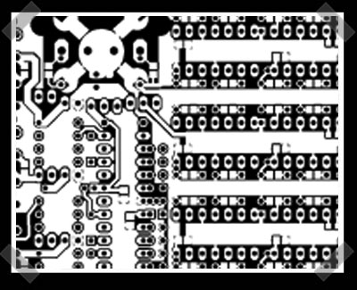
[Waggy] submitted this handy device for his entry. It uses several 556 timers to clock a driver chip that drives the mosfet output. If you’re not familiar with PWM – think of it as a six channel motor speed controller, but far more flexible. [Waggy] did a nice job writing up the details on the board – definitely a strong entry.
15 thoughts on “DC Entries: Six Channel PWM Modulator”
Leave a Reply to DarkAxi0mCancel reply
Please be kind and respectful to help make the comments section excellent. (Comment Policy)


first commenT!
nice hack a day logo on the board.
is this PWM externally adjustable(say with a pot)? or will i have to change resistors to the 556 to vary the width of the pulse?
i’m not an EE so i can’t really read the design, but i didn’t see any sort of variable timing device. definately cool, but would be cooler if it was easily modifiable.
oh and it does appear adjustable seeing as how there are two pots on the parts list to adjust frequency
“Flame Emitting Transistors” lol
Seems like massive overkill to me. How often does one need individual control of frequency for *each* channel, or PFM instead of PWM?
It appears the way this works is that for each channel, the 1st timer runs in astable mode to produce the operating frequency, which triggers the 2nd timer in one-shot mode to produce the pulse-width. Unfortunately this means that you can’t adjust this to 0% or 100% PWM if needed. As the author noted, if you try to exceed 100%, “strange things” will happen – but I’d be wary of even getting close to 100%, as *twelve* timers and six mosfets banging away would make for a very noisy circuit!
Personally I would have used *one* 555 to produce the frequency for all channels, and one comparator for each channel of PWM. Each comparator would have an input connected to the positive side of the 555’s timing capacitor (which produces a triangle wave with asymmetrical rise/fall), and the other input connected to a potentiometer’s wiper terminal, with the pot’s end terminals connected to VCC and GND, for duty cycle adjustment. With that, you could reduce chip count for 6-channel PWM generation from 6 to 3 if you use quad comparator chips (with two comparators left over), and also be able to set full 0%-100% duty cycle. Then I’d use the recovered board space to add some LEDs for visual indication of approximately what power level each channel is set to. Mmm, LEDs! :)
Of course, I’m just being an armchair critic and didn’t take the time to produce an actual circuit, a great webpage and supporting files – so credit and props to the author for his hard work and sharing it with us.
i had a bit of a look, but is there a wire diagram anywhere on the site?
aggree’d, maybey i missed it, but, if not, this really needs a wiring diagram
a picture of the finished result would be nice, also, sweet hack btw
could someone elaborate on the “Automobile or Car Stereo Disabler” potential? I would love to shut down those jerk faces who decide to pollute the air with audible crap.
[darkaxi0m] & [wolf]: ask and ye shall receive. a gif of the schematic (as best i can do with eagle; what a pain) is now linked off the index page . i apologize, for it is rather messy because of all the optional parts and the 9-pin pot mounting pads combined with me having never used eagle before. sorry, [wolf], i can’t etch pcbs right now and am embarrassed to put up a pic of the breadboard prototype showing how to violate nearly every warning i posted.
[slakwhere] & [kevin]: yes, all six channels are independently adjustable. [darkcobra] explains it well. also, [kevin], you can find the (hand-traced) logo in one of the *dw.lbr files in the zipped eagle files off the index page.
[darkcobra]: thanks for the detailed comments. i agree this circuit would be overkill for many applications…except the ones i’d like to use it for myself. these typically involve some mix of lights, fans, pumps, or motors with little in common except being direct current devices and the likelihood they will be powered off of a solar panel or batteries. it’s usually easy to get the voltages needed, but invariably the devices have too much oomph at full power. for a quick one-off i’d rather be able to easily provide whatever power modulation frequencies the devices i have on hand would prefer than to try to put together a set of frequency-compatible devices. but maybe this is just me. i do really like the power-level indicator idea…hmm…i think i figured out how to do it without blowing up the leds regardless of the timer voltage used…now where to place the leds?…
Thanks, its alot easier to read schematics than try to follow the traces, when breadboarding in perticular.
i have to admit i’m not the hardware hacker I used to be, but when i see a project like this in unison with the technical discussions it makes me wanna break out some parts and dream up applications.
thanks much folks for keeping the gears turning so to speak.
(first comment boy can go to hell. I propose the removal of the number 1 from the comments board, because who crows about being number two anyway?)
HEY will, it seems you forgot about the contest at all…at least you could declare a winner…if you dont want to decide, look at the one with best comments!
good one!!