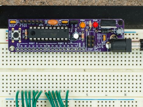
[John De Cristofaro aka Johngineer] uses various ATmega microcontrollers in his electronics projects, but he finds himself reaching for an ATtiny2313 or ATtiny4313 more often than not. He got tired of having to wire up pin headers, capacitors, and the like each time he started a project, so he spent some time designing an easy to use breadboard platform around the chips.
Inspired by LadyAda’s Boarduino, his BB313 board features FTDI pin headers, an ISP programming header, a reset button, along with breakout pins that plug directly into any breadboard. Aside from sharing a similar layout, [John] says that the similarities end there. His board is designed for designers who program in C or C++, so Arduino code won’t run without some substantial modification.
The board looks like a pretty handy benchtop tool, and we’re pretty sure it would be a big time saver for anyone who uses these chips with any frequency. [John] says that the board cost about $6.50 to make when he put it together, but that prices might vary slightly depending on where you have your PCBs made.
Be sure to swing by his site if the design looks like it might be helpful. He has made the schematics, a bill of materials, and all the rest available for the taking.
[via Adafruit blog]


The modifications aren’t sooo substantial! It’s pretty easy, actually.
http://toasterbotics.blogspot.com/2011/08/attiny2313-with-arduino.html
Oooo purple PCB
Looks good, love the mounting holes and the clear silkscreen labels.
just FYI: I’m using http://www.pollin.de/shop/dt/MTY5OTgxOTk- + IDE/PATA cable + http://www.pollin.de/shop/dt/MjQ5OTgxOTk- for attiny/atmega breadboard stuff
This looks really nice, it doesn’t block 2 or 3 rows like the small arduinos that are ‘breadboard compatible’ compatible yes, but not so usable if you’re trying to plug more than 2 wires right into the row of contacts you need rather than making a jumper stack elsewhere across the board. The only things I would change is add another GND on the other side of the ports and possibly break-out the raw power into the header as an optional populate since it’s right there already.
I usually use 2313’s as well, I like this idea and might have to build one. Great project!
@nova: there are a number of ground pins you can use on the left side if you need them. the FTDI port has two of them on the bottom, which are grid-aligned with the pins on the right. Or, you could just solder wires to these and plug them into the board wherever you like. The easiest thing to do, though, is just run VCC and GND to the breadboard power strips and be done with it.
A number of people have mentioned breaking out the raw input voltage, so I did. The new “revision D” board is now online (at the GitHub) with a Vin pin above the VCC pin for just this purpose.
Oh, I also meant to say thanks to everybody for the warm reception and great feedback — I really appreciate it!