Integrated electronic modules like counters and displays are convenient and space-saving, which may also make them easy to take for granted. [Nagy Krisztián] demonstrates this by making three very different digital counter designs, each breadboarded with a 7-segment LED display. Push a button, and the displayed number increments by one for each press. It was a personal project that ended up educational in more ways than one.
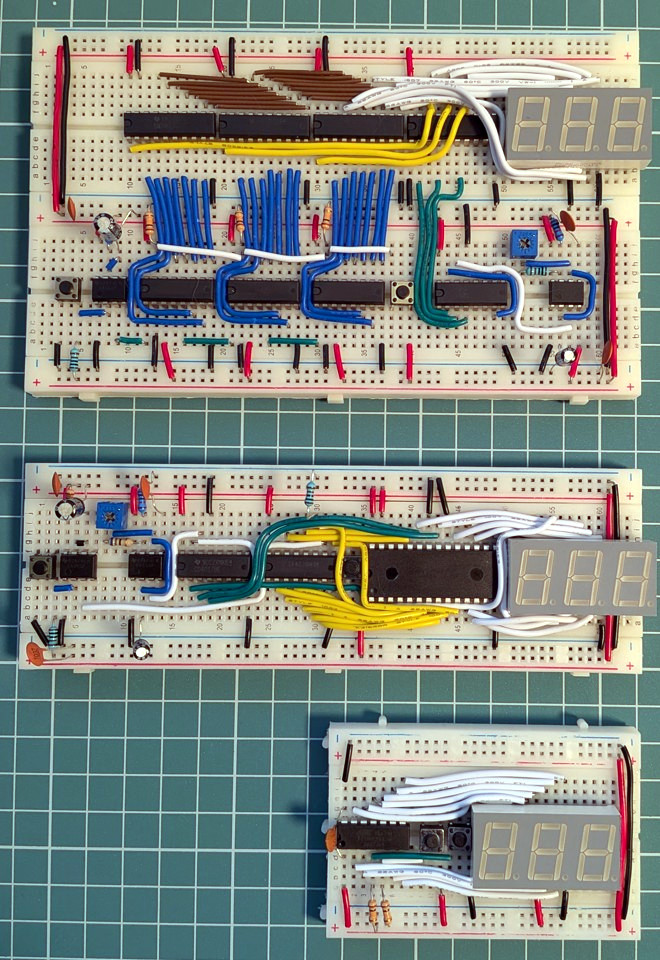
The first version uses discrete components only, and even though it handles the counting with CD4026B decade counter ICs instead of building counters from scratch with NAND gates, it’s still by far the largest of the three. The second version simplifies driving the display with an AT28C64B EEPROM acting as a sort of hardware lookup table translating binary counts into 7-segment digit display patterns. The third uses an ATtiny24A microcontroller, and unsurprisingly has the smallest footprint.
All of this highlights two things. One is that implementing even a simple counter and 7-segment LED readout is a nontrivial affair when one gets right down to it, even when taking advantage of purpose-built ICs. The second is that the complexity that is on full display in the first version doesn’t simply disappear as the footprint and component count goes down. Rather, it moves into software and other infrastructure, like the need for compilers and chip programmers.
The whole thing is both educational and a reminder of how good the average hardware hacker has it today. There are so many effective electronic assemblies, available to just about anyone at low cost, that it can be very easy to take it all for granted and forget just how much breadboard space and wires were needed for even simple-seeming things.
[Nagy] is certainly no stranger to dealing with a lot of wires, as we’ve seen when he fooled a 286 processor into thinking it was plugged into a functioning vintage motherboard.