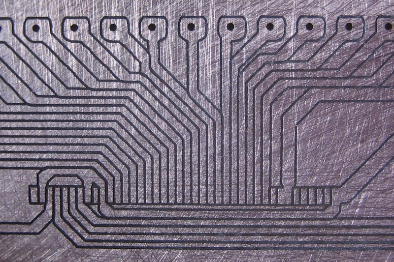
Let’s all slow clap for [Daniel Taylor] who, after a long journey, got his home built PCB mill up and running with remarkable precision. That’s 10 mil traces with 0.5mm pitch pads. We’re impressed! The board will be used for breaking out the connections of an LCD screen he has on hand.
After seeing a CNC project as yesterday’s Fail of the Week it’s nice to look in on one like this that does some amazing stuff. In fact, [Daniel’s] creation has been working for months already. The link above is the project log he kept while hacking, tweaking, and retrofitting his rig to get the level of precision he was after.
Improvements include swapping out drawer slides for proper linear bearings and completely reworking the Z-axis along with a motor upgrade. For those that aren’t fans of the reading (how did you make it this far into this feature?) you can take a quick look at his image gallery which includes captions.


Why would you slow-clap? His mill is working…
Maybe we think it means different things?
http://www.urbandictionary.com/define.php?term=slow%20clap
I see this as a come from behind victory as he had to go through several iterations to get to this level of performance.
I think people are mistaking a slow clap for a golf clap.
Ah, see, for me a slow clap is a sarcastic thing [see, for example GlaDOS’ slow-clap circuitry in Portal 2]
NO! NO! NO! NO!
A slow clap is what happens when the Six Million Dollar Man and the Bionic Woman use their bionic arms to single hand clap with each other at bionic speed.
As we all know, bionic speed is always slow mo.
Now THIS is why I read Hackaday … clever references to 70’s TV and slow clapping! ;-)
for those who really wanted to know without reading, the Bit he uses is a Tapered Ball End Mill – 10 degree .010mm, an expensive little bit!
I’m not sure where you read that… I used a 0.1mm-tipped, 30-degree bit that was ~$10 for a 10-pack on eBay.
Very good precision for diy, impressive :)
I don’t get why we’re slow clapping :S
This is really remarkable, after reading a bit I now understand the “rock solid” description in the title. This guy here uses solid core aluminium all over the place! No wonder the machine is so stable. I guess it can even withstand quite a few temperature variations in the mill itself.
Now it is just a shame he does not use proper SI engineering units in his article. The Internet is International, one should never forget about it. Imagine what it was if everyone started writing articles with its own unit of measurement – mine would be penises.
His components are all imperial, why on earth would he build in metric? That’s how space ships are lost.
I find it much easier to build things in imperial units. Base-12 makes it easy to find halves, thirds, etc. Metric turns that into repeating decimal nonsense.
The argument about division is really not that important, to be honest. You can get by just fine using decimals.
I do, however, wholeheartedly agree with you about the finding components in imperial. If I wanted to build something in full metric units, it’d cost me 3x as much to acquire the components, and my fabrication shop would be confused as all get out.
Hi Mike, I did not know it was that hard (and expensive) to find components in metric.
Decimal inches work just fine, too. Most digital micrometers read out in thousandths, and machinists have been working with those units for a century or more. (Although I’ve never seen anyone go the other way and use fractions with metric, the 300mm “metric foot” for furniture and construction dimensions, which enables easy subdivision into thirds, lends some validity to the need.)
As for pricing and availability of metric stuff, that varies a lot with where you live and where you’re shopping. Often, inch-sized components are available from numerous shops, while metric versions are special-order or you have to go through an industrial supplier, for whom cost is not a strong factor. As long as you’re consistent within a design, it doesn’t matter.
However, sometimes there’s no clear choice. If your parts are measured and placed on a 0.1″ grid, but your software is doing math to derive motor-pulse-counts to drive a metric lead-screw, you’ll end up with a repetitive “stairstep error” in certain situations. If other parts are measured in millimeters, you’re gonna have some error no matter which screws you use.
Electronics is in decimal inches supposedly because printers (typesetters) work in pica, y’know, where the ‘P’ in ‘PCB’ comes from.
The typical pin spacing is 1/10th (2.54mm), or 1 pica.
There’s no real reason to change it so no-one has (apart from the occasional Russian 2m pin spacing). That said most SMD stuff is metric, not like it matters much either.
Imperial sucks because it’s fractions, decimal is much easier – hence decimal inches and why we like metric. No unit conversion in metric either, you simply work in mm (even in construction).
A lot of material is metric, and merely marked as the closest imperial measurement, so a 3mm sheet is sold as 1/8th and so on. The reverse also happens, it pays to be wary – especially when buying CNC parts like bearings and spindles – it’s all metric apart from a few ‘standard’ sizes like 1/4″ & 1/2″ shafts. That 3/8″ shaft? Probably 10mm.
it’s not, at least not in mainland EU.
I assume other posters are using that old “if you don’t mention a region it is USA” rule
That really depends on where you live. I myself live in Sweden. Very few things are measured in imperial units here. Building things with imperial measurements gets expensive quick, an then you get laughed at.
I have a car that was built in Sweden and it is Imperial. I don’t think the Sven that put it together was laughing that day either.
It could be worse.
A few years back the US Government decided that there should be a period of years for US industries to transition from Imperial to Metric. So there is a least a decade of automobiles built with both Imperial and Metric bolts and nuts.
Politicians and Bureaucrats that pass stupid regulations like that ought to be put in jail for the same period of time that their stupid policy exists. The regulation by the way failed as the US is still dominated by Imperial measurements.
People should realize that which ever unit of measurement dominates a region will be the cheaper way to go. In the US, it is still Imperial.
Actually we did change in 1975 but after about 2 weeks of buying gasoline by the litre Americans freaked out, so we changed back. Af far as the mixed SAE and metric cars go that is because they were being assembled in Canada.
Not all of those cars were built in Canada, US made was the same way.
That isn’t how I remember it. I was working in a few different garages back then too.
Maybe it depended on the make and model and my brothers and I just ended up buying the mixed ones. Unless those metrics just annoyed me so much that it seemed like every car I owned and worked on required both an Imperial and Metric set of tools. Excluding the 69 ford that is.
Spaceships are lost because NASA worked with design parts in SI units while a contractor used imperial [2]. NASA issued a public statement quite a while ago on how SI is their standard [1].
Unlike imperial where you use fractional mess (leading irrational numbers). In metric you specify a target precision for your project and then you can convert any unit into metric, rounded to the closest precision. In this project, the measurement in micrometers would have been more than enough:
20 mil = 508 micrometers
0.015” = 381 micrometers
0.03 inches = 762 micrometers
As you can see, all your different imperial units translate into an integer 3-digit number in a fixed unit called micrometer (um). I don’t see why is it a big deal to convert imperial to metric and work from there. Another HUGE advantage of metric is that you can use the scientific notation and greatly simplify calculations with numbers with different orders of magnitude [3].
Just because you are used to work with your rudimentary units, it does not mean they are efficient or better in any way.
[1] http://www.nasa.gov/offices/oce/functions/standards/isu.html
[2] http://en.wikipedia.org/wiki/Metrication_in_the_United_States
[3] http://en.wikipedia.org/wiki/Scientific_notation
I actually won an award at my state science fair for use of the SI standard. Believe me, I know how clean it can be especially when crossing measurement domains like length and force. I built a rocket test stand where a test weight of water (conveniently 1gm/cL) was used to find and compare thrust.
However, I live in the US. Parts and materials are sold in imperial units unless I pay double or more for metric hardware. If I’m building a porch, I will not be working in micrometers. Nor will I be using a dial indicator or a micrometer. Tape measure or story sticks work great and keep the numbers simple (I’m not going to be adding odd 3-digit numbers while I’m on top of a ladder). I don’t have any need to convert to different powers of ten to get that done either. Machining, of course I use decimal inch because my tools are built that way.
My argument is that we work in the system that fits the application and available tools/materials. Converting a CNC design to full metric while the hard parts are imperial is just introducing a possibility for error for no clear benefit.
>>>
Converting a CNC design to full metric while the hard parts are imperial is just introducing a possibility for error for no clear benefit.
>>>
The only things that matter depends on what is being used as the drive system.
If using lead screws, swapping imperial lead screws with metric and imperial bits with metric is pretty much all that is necessary. Then there’s the material issue, however, if you’re milling a smaller part from over sized material, the unit of measurement that the material comes in is irrelevant. I don’t see anyone trying to mill a part on a machine where the part is bigger than the capacity of the machine, so a bit of recalibrating after the part swaps and the mill is transformed.
The ideal would be to build the conversion within the software itself so that the software has both Imperial and Metric and even SI configurations. Then it is just a matter of changing the configuration and homing the machine to set it up.
You talk like there is only one metric system Vs imperial.
An example of how there is more than one metric system:
an 8mm standard bolt in the EU has one pitch.
An 8mm standard bold in Japan has a different pitch.
But both systems have an 8mm fine thread bolt and those are the same.
Metric is not the monolithic One Thing vs Imperial.
I use both in my cnc machine shop, but convert to imperial for measuring because our people have done it that way all their lives, and it is prohibitively expensive to maintain dual sets of all measuring instruments–1 in metric and 1 in imperial.
Metric stock is all but unavailable from US steel suppliers in either round or hex bar form. Even the metric stuff comes in as 12′ bars (which is 3,657.6 mm–not an even number).
I would get laughed at if I were to ask for some 50.8mm x 101.6mm lumber…instead of 2×4’s Which don’t actually measure 2″ x 4″ anymore anyway.
Live and let live, and when in Rome, use Roman numerals!
I’d live, and let live but the metric zealots seem to want to push the Imperial system out more, and more. So they can drop dead!
You stated:
*20 mil = 508 micrometers
*0.015” = 381 micrometers
*0.03 inches = 762 micrometers
*
*As you can see, all your different imperial units translate into an *integer 3-digit number in a fixed unit called micrometer (um).
Except the problem is you are starting with rounded numbers to get your 3 place numbers. Suppose you carry 1/64″ out one more place from .015″ to .0156″–now it is not 381, it is 396.24 micrometers.
Taking to 4 decimal places is reasonable as that is the least accuracy that my cnc machines have (all 11 of them). Several go to 5 or 6 decimal places.
If you take 5 or 6 decimal places in imperial it equally fails to come out even in micrometers.
When I built my cnc I use both imperial and metric parts, whatever linear components I could find on ebay for cheap. Most are metric being made in Japan or Germany but the NSK ballscrews I used on my gantry was mixed. The ballscrew was 5 turns per inch, the end bearing shaft was 16mm in diameter but the threaded end nut was a imperial pitch. How’s that for mixing your units. I use imperial units when drawing in Solidworks since thats what I am used to. The CAM program doesn’t really care, it’ll just spit out the g-code to whatever you choose, either metric or imperial. The CNC controller, MACH3, accepts either one. So ya just build your cnc with what parts you can find. Doesn’t matter if it is wood, metal, plastic, imperial or metric. The most important thing is that you built the CNC yourself. If it works and does what you want with it, than all the better.
JIm
Provided that the program is written correctly, and that is not a relative statement, then you are good to go.
I have AutoCad 2012 and if you start a project in Imperial and convert it to metric, the units will not be properly converted to metric and vise versa. That is an improperly written program.
As easy as it is to make errors when converting from one unit to the other, those things that computers do without hesitation should be done by the computer. Converting measurements from one unit to the other is one of those functions.
Unfortunately, there are way to many people that believe the harder something is to use, the smarter they are in having the ability to use it. In their little minds, a highly skilled Surgeon is an idiot if he is unable to write a complex program or use the command prompt.
I’m of the opinion that the easier something is to use, the more people and hobbyists there will be using it and that makes the designer/developer smarter for having expanded his or her market base. And those who expect the vast majority of people to become advanced technical users are stupid for expecting the impossible to happen.
Imagine the if you will automobile manufacturers demanding that the average driver be able to rebuild the internal combustion engine that resides under the hood of their automobile. It’s just not going to happen, and expecting the average driver to pursue that level of expertise in order to drive an automobile is just plain stupid.
All units are arbitrary. They are merely references to a known quantity. There is no more truth in one objective unit of measure than another.
Expecting everyone to conform and ‘never forget’ about conforming has led to more horrors than good. I see people that are in that train of thought no better than any persecutor of race or creed, because ‘it is a shame we are not all the same and THE STANDARD as I define it should be respected above all else’
I use whatever measurements my parts came in. Since I started with hardware-store components, my axes are all in Imperial units. Many of my bits come from China, so they’re metric.
And as mentioned by another poster, finding metric tools/parts isn’t necessarily cost- or time-effective.
So, that looks like a breakout for an FFC/FPC cable. I can’t stress enough how much I want one of these machines.
I don’t think the units matter as long as you are consistent. I remember the time someone I was working on a project with tore apart part of the project I had made. It was very reassuring when she said, “It was supposed to be 36″ off of the top edge, but one side was a centimeter off.”
Simplified the message seems: do not use MDF as base material if you want pinpoint accuracy.
As already suggested in the ‘fail’ article comments and now confirmed it seems.
Perhaps it might be better to say don’t use MDF for this style overhead gantry CNC machine? While popular it is my belief that there are basic flaws in the design that MDF exaggerates, but stronger materials compensate for. This design is just basically unsound. The fact that many people make it work despite deficiencies isn’t really important either. That doesn’t change forces, leverage, or balance in any way.
Care to elaborate on that? Honest question- I’m all for making things better (if/when revisions come around).
I personally don’t see any immediately better design to use (though I’m admittedly tired at the moment). The spindle is cantilevered more than I’d like, though that’s about all that comes to mind. Maybe you’re saying an X-Y table would be better?
The MDF is literally only used as a surface to mill on, and even at that it’s sitting on top of a supporting structure. It was chosen specifically because it’s soft, meaning I can re-level the table easily, and it won’t make cutting out the PCBs any more difficult than it needs to be.
If this works then message me from YouTube I can elaborate and perhaps make your motor drivers run like this:
https://www.youtube.com/watch?v=fHPKaHLzXes
That wasn’t an MDF fail, it was a ‘basic woodworking’ fail.
There are screws & inserts made for MDF, use those (they have large threads). If you must screw into the sides, the other face should be rebated, and make sure your pilot hole is correct to prevent splitting. Or change your design.
Here’s a torsion box (something that needs to be extremely rigid and stable) made from MDF by a master craftsman: http://www.djmarks.com/stories/djm/torsion_box_assembly_table_94697.asp, video here: http://vimeo.com/5082731
Those saying “MDF = fail” are the real fail.
I think one thing that helped the precision was the sanding. With thinner copper clad you can cut through quicker and the 30degree angle of the mill won’t force you to cut as deep allowing cuts to be closer together. Nothing wrong with that. Just sayin’…