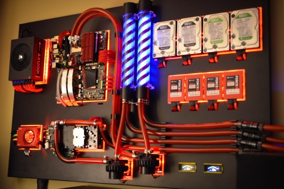
When Overclock.net user [Show4Pro] decided to upgrade his “old dusty rig”, he eschewed the conventional PC form factor and instead built an incredibly sexy custom wall-mounted case.
The six sticks of RAM, quad HDD/SSDs, and dual Radeon HD7970s are enough to make all but the most hard core gamer blush, but that was only the beginning here. Using a Dremel tool, Show4Pro cut the frame from a piece of hardboard and coated it with a mock-carbon fiber vinyl sheet. This backdrop acts to both hide the (many) cables and provide structural support to the components. Custom light guides cut from an acrylic sheet are back lit with LEDs and serve as a border for each of the components.
Laying all of the boards flat on the frame required the use of PCIe risers to move the video cards away from the mother board. Long PCIe connectors are very susceptible to EMI though, and Show4Pro ran into a few stability problems that he eventually had to resolve with some high-end shielded risers.
Besides that one minor hiccough, the project went off without a hitch and it looks like his 100+ hours of work have really paid off.
Via Reddit.


pci-e uses differential signalling. Shouldn’t the pci-e rises be using twisted pair cables?
risers*
The flat cable works for most of time if kept reasonably short and is dirt cheap, so that’s what Chinese manufacturers are making ;-)
Thought the same, but then I googled and found PCI-E impedance = 100Ohm and normal ribbon cable impedance =120Ohm, so not that much of impedance mismatch
Ribbon cable works pretty good for most instances where you need twisted pairs. When I modded my Xbox360 with a VGA port I used ribbon cable and put a ground between the RGBHV lines. I was surprised it worked considering how sensitive the VGA coming out of an Xbox360 is to noise.
Yeah, when I made a xbox 360 AV to VGA cable, it had really poor quality video until I salvaged a cable shield and put it on this cable and grounded it well to both ends. It was a little surprising.
I’m not real great with the shielding stuff, but aren’t you only supposed to ground one end of a shielding cable? Isn’t that what they do with USB?
We have a special word for a conductor grounded on one end, it is called an antenna.
Can you explain why they do it with USB in simple terms then? This is what I’m referring to: http://www.microchip.com/forums/m267325-print.aspx
I cannot explain because I have never given it any thought, nor do I have any knowledge of the matter. I’m sure whoever designed USB had their reasons for doing things how they did them. I can only speculate as to exactly what those reasons were though. Maybe to protect against ground loops, or to isolate one device from another which may have a higher potential ground? Perhaps something else entirely. I’ve no direct experience working with USB beyond plugging devices into the ports, like many others do. I still like parallel ports better. I’ve made a port buffer for one of those too.
I can say this now, the metal shields on both ends of a USB printer cable have continuity between them. I just measured it with an ohmmeter here. So whatever hocus-pocus going on is going on inside the devices themselves. For now I’ll take it an an article of faith that one end is not connected to a chassis ground based on what I’ve read at the link you’ve supplied.
Mostly because I’m not interested enough right now to rip open a printer, or something to investigate further. USB really isn’t my bag, I’m sorry.
You’re right in that grounding at one end effectively makes a cable an antenna, that is exactly why it is important to ground at and end with low-impedance and not at the end with the sensitive receiver circuit.
It’s ultimately a trade off and ideally you design systems where ground potential is equalised and return currents never travel across the shield, but in cases where this isn’t possible like most single ended circuits it is far more preferable to have an antenna going back towards the transmitting device than it is to have a ground loop. It’s quite application specific.
They tends to wire 2 ribbon cables, one from side A and one from Side B
in those risers. The PCIe pinout if you look at Side A or B has 1 or 2
grounds on both sides of a differential pair to isolate them from other
signals. This arrangement is pretty good for signal integrity.
The ground as a shielding effect for capacitively coupled noise and the
extra separation to reduce magnetically couple noise. The ground signals
also work as return path should there be some slight mismatch in the
differential drivers.
Twist pairs are used when you want external noise coupled to both wires
in a more or less equal manner. Due to the grounding arrangement, that’s
not a big issue.
The part that ribbon cables isn’t spec for high frequency and more so
for the Chinese cables. Who knows what attenuation/impedance
characteristic looks like over the frequncy. But hey it is less than
$10.
(To be honest, I wouldn’t even dream of this being possibe after reading some of the PCIe-spec. I mean, even… look att the requirements for PCBs… But I guess the free space around the cabes is the thing that makes this work.)
One thing I don’t understan is why ground would work good as an “insulator”… I would understand it, if it was connected only in one end. But if it is on both ends, wouldn’t it let through a current of (sum of all incoming current)/(number of return ground wires)? Let’s take an example of an on-board GPU fan, it would draw current from the +5v in the cable and then return current through all ground wires, probably in an equal fashion as all wires have roughly the same resistance.
I’m a beginner in electronics, so I could be wrong anywhere and everywhere ;)
Did you see isolate and read insulate? The author maybe should have used the word shield. As grounds used to block interference are usually called shields. Either that or I’m seeing things.
Hmm, I didn’t even know there was a difference between isolate and insulate (in Swedish, which I’m natively speaking, they mean the same). What I really meant was “something between that will block interference”.
It is a matter of geometry, if your interference is from a far distance
relative to the separation between a diff pair, even on a flat cable the
distance from it hence (magnetic) coupling would be more or less the
same.
DC current would be distributed based on the DC resistance while AC
(high frequency) current by the impedances. Roughly speaking the
“shortest” path would have lower inductance and carry more of the
current.
“Roughly speaking the “shortest” path would have lower inductance and carry more of the
current.”
Can you break this down/explain this further (Pretend I’m in 4th grade)?
Essentially, the larger the current loop (from the signal and its return
path), the higher the inductance there is. So AC current tries to flow to
minimize this.
e.g. If you have a signal and ground right next to each other on a
ribbon cable and some other grounds further away. The “shortest” path
for the return current would be the ground wire right next to it as the
return current would flow in an opposite direction canceling some of
the inductance.
The actual math/physic is 1st years University level stuff and covered again in 2nd years.
Not really what I meant… It was more that it might be stupid to have sources of interference near the signal cables, even if they are in a diff-pair. (Or Isn’t it?)
And why would it not matter? Let’s say the separate cables in the flat cable are laid out like |a||b||c|. Wouldn’t the a-cable in the diff-pair a|b be affected at least half of what b would be (or, rather, exponentially as the field attenuates with (distance)^2 or something like that)?
I think I missed an important point in my first post: the GPU fan is PWM-controlled. I didn’t think about that DC currents don’t cause electromagnetic interference, so let’s add that. The fan was just an example anyway to have something to visualize, there can obviously be a lot of other things that turn on and off on a graphics card.
We can probably assume that the grounds are connected together on both ends of the flatcable and that each individual cable component is equal => the current paths all have the same impedences. So there would indeed be some current through the ground wires (approx. the same for all). The question here becomes either:
* Does the ground not interfere with the diff-pair that much at all to make a difference, even in a PCIe-bus?
(or, if true:)
* Why have a ground cable there anyway? Vcc or some other signal would work as good (another signal might mean even less ringing compared to Vcc/GND, so why not cut straight to the next diff-pair, leaving something in between out anyway?). I mean, having the least components possible seems to be something of the big design goal in the cheap stuff you buy from china.
(The point I’m trying to make is that GND is not “void” here, it is something that carries a current – probably one that’s changing (DC + AC component). I think the tricky part here is thinking that GND has DC-characteristics (voltage), but it really has AC-characteristics (current), since current, not voltage, is what will induce an electromagnetic field.)
You need to tell my stepper motor drivers that DC currents don’t cause electromagnetic interference because I don’t think they got that memo.
>Vcc or some other signal would work as good
Only if they are connected to the VIO of both the PCIe drivers/receivers
on opposite side of the connector as any imbalanced currents of the diff
pair would flow through them. Since this is not a practical thing to do,
ground is preferred.
pcf11: Bring them here and I’ll see what I can do *fetches the large testa coil*.
tekkieneet: Good point, but why not leave it out and have a smaller cable with fewer “inner” cables?
Holy shit.
That. is. f*cking. gorgeus!
Except, not really. Sloppy super long hoses everywhere with the clamps, pumps mounted not even at the same height and with crooked hoses, barber-stop like reservoirs that don’t fit the whole look, fugly wiring behind the panel, ugly yellow gauges at the bottom right that just don’t fit in, etc.
I’ve seen far better “case mods” (like some on million dollar pc) and those didn’t really belong in a museum either.
Looks Excellent.
I can’t help but laugh that he thought for even a second that the cheap risers were going to work in a daisy chain. I mean, really?
Maybe HackaDay needs to run a series of articles outlining the basics of high-frequency circuits theory.
There are websites/mailing lists that address specifically about high
speed signal integrity for people with the necessary backgrounds.
Even within the community, there are different schools of thought of
doing thing. Worst part is not followed everything to the letter and
mixing them up.
IMHO it is not a subject to be dumbed down for the general HaD hacking
community. General rules of thumbs are bad as they tell you the HOW, but
not WHY and WHEN the rules apply (and not apply).
It can be boiled down somewhat. Obviously a complete understanding requires a lot more knowledge than the average hobbyist will have, but there is a lot you can learn that isn’t so complex. Henry Ott Consulting has a “tech tips” section of their website that is a very good introduction to these concepts: http://www.hottconsultants.com/tips.html
My beef with the “rules of thumb” approach over time people develope a
superstition when they do hardware designs without knowing the WHY and
WHEN.
I have seen that at some places. Over time that has done more harm than
good because it suppresses thinking out of the box and innovations which
are what drives technology.
Might want to visit Dr. Howard Johnson’s website: signalintegrity.com
if you are interested in the subject.
I hope HaD doesn’t start doing articles outlining theories, I like looking at pictures of actual stuff.
absolutely beautiful… wow, wow, wow. I’m stunned.
But wheres the flux capacitor?
And what are those barbershop lights?!
Joebin Cummings: “And what are those barbershop lights?!”
I’d hazard a guess they’re flow indicators for the water cooling
They’re an acrylic tube reservoir with a coloured double helix in them and finally a CCFL tube up through the middle.
May the dust be with you !
And swished away in moments with a feather duster! In a standard PC box it just accumulates.
And burn your memory stick with static electricity. Been there, done that :-/
Why hide the busses and power and expose all that plumbing? It’s a computer not Kenner’s Hydrodynamic Building set. It looks like a model of some nightmare chemical processing plant, with pipes runing off to a river.
thats genius. i now have a subject for my next model project.
I kind of like the concept of computer as a water heater with benefits.
I haven’t got enough room for a system like that. Maybe I’ll stick my Raspberry Pi up on the wall.
LoL, indeed :) If it’s in a sunny place, you could even mount a solar panel on top – Like fancy art museums and private collections do with lights – To power it :) Add a wifi dongle and you’ve got a fully accessible computer on the wall with 0 wires :)
I like. I built something similar (but not nearly as good looking) for the IT department display case at the tech college I used to teach at. It was complete with a monitor and ran a .ppt presentation describing each part and its interaction with the whole of the system.
The only thing my system had that this one doesn’t is the clear plastic cover that allows you to see the spinning hard drive platters and tone arm. But if this is actually a usable system, you probably wouldn’t want to risk it.
All that just for some litecoin mining :)
Hehe, I jest! Seriously, not only is it stunning in terms of quality, it’s a pretty awesome rig in general aside of the “case” :) Nice job!
That sure is pretty. The barbershop poles looks a bit out of place in my opinion, though.
I think it belongs to the Charley’s chocolate factory.
Absolutely Awesome. My hats off, and kudos sir on an awe inspiring project.
Very nicely done
It looks pretty and is nicer than my PC, but is this really that much of a hack? He assembled a PC and mounted it to some hardboard and acrylic.
Extending the PCI-e bus like that is very much a “hack”!
Not when you can buy the parts off the shelf. It’s already done quite often in the small form factor builds when the card is taller than the case.
how about this: https://www.dropbox.com/s/be1sa3dmacacokr/2012-07-29%2003.22.54.jpg
to make applying the sticker less difficult, use an air-hockey table with the fan reversed, making it suck. put the sticker sticky side up, then lower the panel on it. easy for me to say not experiencing it, but that’s an approach i’d suggest.
this build is fantastic! well done!
case mods are not hacks.
It’s not a case mod. It’s a custom case build.
What case?
There sure is a case, it’s where all the cables are hidden.
fine. case builds are not hacks. If you go to the store and buy a bunch of stuff and use it exactly how it is intended, then you havent hacked anything. at best youve assembled something.
Ergo, this is a hack. The parts used were “intended” to be installed in an ATX (or other standard factor) case. The base board is a custom fabrication.
I one time put a MiniITX board inside a manilla folder which was cut and taped in to the form of a case, because i was too cheap to buy a real case. That wasnt a hack, this isnt either. God people here are easily impressed.
so you’re saying you’ve built something better? please share. i consider this a hack until you’ve wowed us with your more incredible version.
First off to all of the naysayers yes, it is a hack. It isn’t my thing but I appreciate the craftsmanship. It is a great job.
I once built something like this with a IBM XT motherboard, as I wanted a demo computer for a computer repair class I taught. But it sure didn’t look this good!
Forgive me if i’m blind, but where’s this second GPU? I can see only one set of extenders (and I wonder about latencies, let alone noise) besides no visible second card…