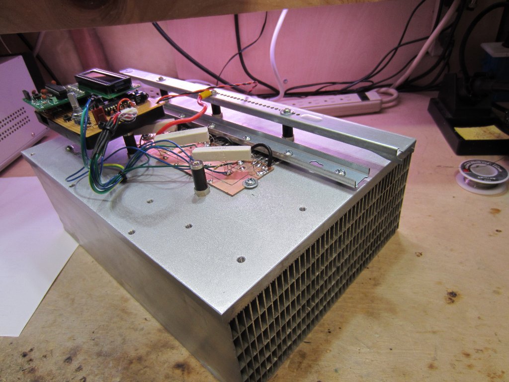
By just looking at the picture above, we’re pretty sure that most Hackaday readers will have guessed by now that much power can be dissipated by this electric load. For those who don’t know, an electric load (or dummy load) is a device used to simulate a load on a system for testing purposes. This is quite handy when measuring battery capacities or testing power supplies.
The heart of the device that [Kerry] designed is based on 6 power MOSFETs, a few operational amplifiers and an Arduino compatible ATmega328p microcontroller. Sense resistors are used to measure how much current is passing through the MOSFETs (and therefore the load), the MCP4921 Digital to Analog Converter (DAC) from microchip is used to set the current command, and the load’s voltage is measured by the ATmega ADC. Measuring the latter allows a constant power load mode (as power = current * voltage). In his article, [Kerry] shows that he can simulate a load of up to 200W.


“Arduino compatible ATmega328p microcontroller”
As opposed to the other kind of ATmega328 that isn’t Arduino compatible? Stop throwing Arduino in everywhere!
Wow are you pissed PO’d the redundancy on with “Arduino compatible ATmega328p microcontroller”? people use redundancies like that all the time my favorite is RPMs or are PO’d that the word Ardunio was used, both the small stuff not to sweat. I have to be pretty sure there is not a conspiracy on the part of hackaday when it comes to the Arduino
Subtle.
I would love to have some help building a current limiting circuit for an Arduino project that needs to be really reliable
Simulate a charge? Simulate a load, surely.
Charge is measured in Coulombs, Power is measured in Watts. This stuff is pretty fundamental, important to get right & I would have expected the author to know better TBH.
my apologies… I thought the english meaning of the two would be the same. edited.
Mathieu are you outside the United States or received an education outside the US? I scrolled to the article to see “Charge is measured in Coulombs” was used in context, but now you edited it I can’t. A charge is measured in Charge is measured in Coulombs, so in context you may have been correct in an article reporting on the project, then again I could be complete wrong on that. I don’t have clue if EccentricElectron resides in the US or not. However I have notice that many of us in the US are unaware that outside the US electrical and other engineering terms are used in a manner we aren’t familiar with. That is why ask your US “status”.
Hey static, I’m french. I made several queries to see if I could simply swap “load” with “charge” but it seems I can’t.
Also in spanish the same word is used for both: Charge = “Carga”, Load = “Carga”
Compare “Charge électrique” to “Puissance électrique”
In case you overload a voltage source, the feedback circuit will open the mosfets more to maintain the set current, then the voltage and current drops more and finally the feedback circuit will to open the mosfets completely until short circuit. This may be a problem. A solution is to feedback the power supply voltage (use a voltage divider to get 5 V nominal) to the DACs reference input. The source voltage is used as reference voltage, so when it drops the current setting will drop accordingly and you can set a overload current that will not result in a short circuit.
or just simply measure the input voltage (as in A5) and look for drops.
then correct the DACs value. –> software only solution
Simulate a load? That is when the light bulb should go off. Or come on rather.
http://www.instructables.com/files/orig/FFC/83YL/GSUSNEUG/FFC83YLGSUSNEUG.jpg
sometimes you need to have a nice controlled load to measure performance of things, I built one to do a 20hr discharge of batteries, find out that china 4.9Ah li-ions are indeed really 1.3Ah. hackaday didn’t do that submission…
Cool! I recently got my hands on a big hewlett-packard load mainframe and have been testing some different batteries and have come to similar conclusions. They seem to be, erhm, somewhat selective about submissions based on…specific…criterion, unfortunately…
I’m curious what you find so out of control with light bulbs.
Maybe the fact that light bulbs aren’t linear resistors?
The resistance (thus load) for a light bulb changes with temperature. And they are not specifically designed to have a constant load, so there is typically some significant variance from the stated specs on the box.
So why did’t you provide a lnk to your project in your comment where yo mentioned it?
I’m confused what China has to do with this project. surely you are aware that US or other companies already choose what Chinese companies they award contracts to.
Ahhh! You forgot to factor in the Chinese>English Ah Exchange Rate!
i for one would have liked to see it. floats my boat
I don’t know about you, but when I’m sitting at my desk, I’d rather look into a 200W resistor than a 200W lightbulb. Also, lightbulbs only come in very limited range of voltage and wattages.
Regardless of what you prefer high watt light bulbs are a lot easier to come by than resistors. As far as wattage goes I’ve found that it is relatively easy to simply add light bulbs to equal the load I am looking for. Maybe I’m just gifted though? heh
High watt resistors are pretty easy to find too. Every major electronics distributor has several types in stock.
On the other hand, if I need a 20V light bulb, I see that Farnell (for example) only has one type available, and it happens to be 150W, and it costs twice as much as a 150W power resistor. The light bulb is harder to wire up, is annoyingly bright, is highly non-linear, can’t be heatsinked properly, is fragile, and has a limited life span.
So, what’s the advantage of light bulbs again ?
Why would you need a 20v dummy load? Dummy loads are about ohms and watts. The voltage is only important if you’re trying to actually iluminate things with it. Generally you’d pick a higher voltage rating that you were planning to use. Generally mains voltage bulbs, which cost almost nothing. The non-linearity might be a pain, but perhaps it’s not as bad if the bulb stays in it’s cold temperature range.
Incandescent bulbs win on availability too. Most people’s houses have some. Although that’s not gonna last long. I saw LED bulbs at Aldi (cheap supermarket) the other day, impressive!
I suppose it depends if you want a cheap hack to dissipate unwanted power from an amplifier while you’re testing it, or a regulated dummy load to measure stuff with.
Maybe I have a 20V output driver that I’d like to test at 10A. So I need a 2 Ohm load.
Mains voltage is 230V, so a 100W light bulb is over 500 Ohms when hot, and maybe 35 Ohms when cold (1/15th rule of thumb). So I need to wire up 17 bulbs in parallel to get close to my 2 Ohm load. A bit unpractical, I think.
And I don’t even any 100W light bulbs in the house, and they don’t sell them in the stores either.
Oh well it sucks where you’re at.
Use a 120V light bulb, it’ll handle 20V just fine. They’re not very bright at 20V either so they should suit a dimwit like you.
Sure, and 120V light bulbs are so easy to get in countries with 230V mains.
I’m glad you pointed out the non-linearity of light bulbs!
IIRC, even the coiled filament has a reactive component as well, albeit small.
(So do wire wound resistors)
Driving 200W into 2 ohm loads is perhaps a bit unusual. It’s not really a universal solution, but it’s something people do sometimes to get a good enough result. I believe that’s called a “hack”.
Well, the project featured here can do 200W, so it’s fair to compare the light bulb solution to that power level.
From the size of the heatsink i was expecting at least a kw, maybe a couple.
200W? dissapointing to say the least
In other words, a disappointing dissipation!
Damn, we appear to have found a whole herd of people who can’t understand why such a device is incredibly useful. These probably are the same people who can’t understand why someone would want a lab supply, with continuously variable voltage and current setpoints (a power supply without a constant current mode is NOT a lab supply!). To them, a set of car batteries is all they will ever need…
How, exactly, would you use light bulbs to, say, modulate a 100Hz squarewave onto the load, to measure the dynamic impedance of a battery under test? How would you modulate a sine wave, of triangle wave, or anything other than just connecting or disconnecting one or more bulbs? How would you suggest to use lightbulbs to modulate the load current to get a constant voltage on the supply you’re testing, or a constant power draw?!?
I sure hope none of you pretend to be (or intent to become) PROFESSIONAL engineers!
Why can’t you just appreciate the design for what it is; an incredibly useful piece of laboratory equipment, simple and elegant in it’s design, while the commercial units are insanely expensive and nearly impossible to find on the used market?
One little note about the design: I’d be a bit worried about the current sharing between the two MOSFETs in each set. A small resistor in series with the source of each MOSFET should help with that.
I’ve build something similar a little while ago, using a rather large IGBT brick, but I blew one of the transistors while dissipating some 600W, exactly because of this issue. In these IGBT bricks, and emitters of the transistors are connected together (mine had 3 transistors each for the high-side and low-side), so it wasn’t really possible to insert a separate resistor in each emitter connection.
It helps that MOSFETs have a positive temperature coefficient, while IGBTs generally have a negative one. When you put MOSFETs in parallel, this tends to automatically balance the currents.
The main reason I used the IGBT was that the high-side was already destroyed anyway (which is why I got it in the first place), and I figured it could easily dissipate a lot of energy without much trouble. More or less a solution looking for a problem, I guess.
I don’t really agree with your statement that the temperature coefficient of MOSFETs will provide reasonable current sharing. The Rsd(on) of MOSFET does indeed have a positive temperature coefficient, but that only really matters when you saturate the MOSFET (like you would in switching operations). The temperature coefficient of the Vgs(th), on the other hand, is negative; when the MOSFET becomes hotter, it will turn on more for the same gate-source voltage, and therefor take a larger portion on the current that should be shared by the two MOSFETs of each set.
This circuit uses 6 IRFP150N MOSFETs; take a look at figures 1 and 2 (on page 3) of the datasheet: http://www.irf.com/product-info/datasheets/data/irfp150n.pdf
It clearly shows that at 125 degrees (figure 2), the drain current is significantly higher with the same drain-source and gate-sources voltages, compared to the 25 degrees in figure 1. With a gate-source voltage of 4.5V, the MOSFET saturates at 5A @ 25 degrees vs. 10A @ 125 degrees. Obviously, the MOSFET at 125 degrees would be dissipating twice as much power.
I think it clearly shows that MOSFETs will still experience a thermal runaway in this application.
Good to know. Practically all my MOSFET applications use them as fully saturated switches, so I wasn’t aware that the gate threshold works the opposite way.
The reason is actually that MOSFETs have internal resistance, whereas IGBTs do not. So you don’t need external resistors when load sharing across MOSFETS.
If you put a scope on the output of the gate-drive circuits I bet they are ringing – ALOT. Page 10 of the LM324N:
“Capacitive loads which are applied directly to the output of the amplifier reduce the loop stability margin. Values of 50 pF can be accommodated using the worst-case non-inverting unity gain connection. Large closed loop gains or resistive isolation should be used if larger load capacitance must be driven by the amplifier.”
He’s got a 1k between the gate and output – that’s good, but the 1nF (1000pF) cap is not helping anything. When driving capacitive loads you have to be really careful about what you pick for an op-amp (and what resistance you put between).
For some really great insight from Bob Pease see the story from Electronic Design “What’s All This Capacitive Loading, Stuff, Anyhow?”
I figured the 1nF caps were part of the feedback circuit, but I just noticed they are directly connected to the source of the MOSFETs, while there should be a resistor in series (or the cap should be connected to the other side of R6). The resistors in series with the inverting inputs (R6, R9, R12) don’t seem to serve any particular purpose to me, except maybe to limit the current during transient events, but in that case they could have been much larger.
It could just be a mistake in the schematic, because I don’t think it really makes sense now. You are completely right that such things should be checked, but maybe he actually did that already, and didn’t find any problems.
That is one gorgeous heatsink! If it wasn’t surplus or something I bet it was expensive. We have long extrusions of finned stuff around here that we use for making test jigs, but I haven’t seen anything with closed passages like that. It would be easy to make your own chill plates with something like that. Nice…
“I used the Arduino board I made earlier”
You are free to make them … but you can’t call your clones Arduino, that is the number one rule :)
So, he needs to call it a Kluino…
My arduino compatible Electronic Load which is for sale on Tindie, cannot dissipate so much as this one, but it can do pulsed loads! https://www.tindie.com/products/jaspersikken/jaspers-electronic-load-r3/