[Malte] just finished a little project for his Wabeco F1200 milling machine: a compact external display for three digital sliding calipers (Translated from German). As you may have already guessed, [Malte] was lucky enough to be able to fit disassembled calipers onto the machine and use them for positioning. Before embarking on this adventure, he noticed that there were similar projects present on the internet, but all of the calipers used had different data interfaces and protocols. The calipers that [Malte] bought have a mini USB connector, even though the interface itself isn’t USB. As he couldn’t find any information on that interface, he turned to his oscilloscope to decode the protocol.
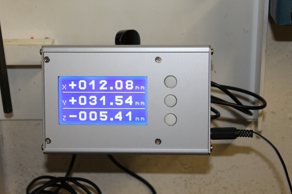
[Malte] then built an AVR-based platform that reads out the three calipers and shows the position data on the dot matrix LCD shown above. The AVR firmware is written in a mixture of Basic and assembler language. The source code, schematics, and other resources can be downloaded from the project’s web page. We are impressed on the professional aspect of the final result.


Nice! Really good looking setup.
I have one set of modified calipers mounted to the cross slide on my lathe so far and one on the tailstock. It’s really nice to have the linear encoders rather than rotary encoders so you don’t have to worry about slop in the measurement as much.
Is this really the best way of achieving this task? I have a couple pairs of cheap Chinese electronic calipers and most of the time when I turn them on I have to re-zero them. Also when I measure things like feeler gauges with them, the reading is often +/- 0.002 (yes I am careful to apply the same amount of force)
Also does anyone know what difference if any there is between the cheap Chinese electronic calipers and ones which cost 5-10x as much like the Starret ones? Are they really worth the extra money? Would I be better off in investing in analog calipers?
I should clarify that for the feeler gauge reading, I was referring to the repeatability of the measurement.
2µm really isn’t much, considering that digital calipers typically only display a 10µ resolution.
There is a huge difference in the marksmanship and tolerances between 10$ Chinese calipers and 120$ Mitutoyo – e.g., you’ll never have to re-zero a Mitutoyo; it’ll also last much longer than any off-brand caliper while giving more reliable readings.
Sorry if I wasnt more clear, but I was specifing fractions of a inch not µm.
Protip: for *inch* decimals, there’s no zero in the ‘ones’ position.
.002 – inch
0.002 – mm
really? you ought to tell every company out there, because they seem to disagree with you.
http://www.grainger.com/product/STARRETT-Electronic-Digital-Caliper-5UAT7?functionCode=P2IDP2PCP
Resolution 0.0005″/0.01mm
Accuracy+/- 0.001″/0.03mm
…and you’re screwed if you want 1.002
Protip: specify your units.
Replying to myself as the comment chain can’t grow anymore… this is how we teach it in the colleges, and (while it should be obvious) this rule applies only to dimensions less than are single-unit. (ie. you won’t see ‘1.002’ represented as ‘1 0.002’ ever)
“In the United States, the standard decimal marker is a dot on the line (i.e., a period or ‘decimal point’). When writing numbers less than one, add a zero before the decimal marker. For example, on a drawing you might define a small length in English units as .032 in., but write the metric length as 0.81 mm.” (note: no zero in English representation, leading zero in the metric representation)
And of course (in NA), if the engineering drawing doesn’t have a ‘METRIC’ stamp on it, assume inches.
Found a copy of the standards, ASME Y14.5M-2009 states:
1.6.1(a) Where the dimensions is less than one millimeter, a zero precedes the decimal point.
1.6.1(b) Where the dimension is a whole number, neither the decimal point nor a zero is shown.
1.6.2(a) A zero is not used before the decimal point for values of less than one inch.
1.6.2(b) A dimension is expressed to the same number of decimal places as its tolerance. Zeros are added to the right of the decimal point where necessary.
‘Matt,’
In NA, we drive on the ‘right’ side on the road, this has impacted also how people walk on the ‘right’ side of hallways and how (generally) the rightmost escalator moves ‘forward.’ While there are no rules saying that you must walk on the right side of a hallway or which direction the escalator must travel (don’t quote me on that one), it’s inherited from the environment.
In a manufacturing environment, verbal and written conversations back and forth between others in that environment oftentimes is based on the rules that govern other areas in the field. I might say ‘ya, we need to use point-oh-two-oh wire’ or ‘ya, we need to use the zero-point-five-oh wire.’ Both describe roughly the same diameter, but it’s immediately obvious to others ‘in the know’ which units are being referred.
Unfortunately you didn’t know what you were talking about in this environment when you made you initial comment, stating +/- 0.002, and my attempt to inform and educate you has lead you to believe that I’m autistic. I called it a ‘protip’ because that’s how us in the manufacturing field (the professionals, or ‘pros’) talk–as an inheritance of the rules that dictate other parts of our environment.
Above all I’m sorry you were raised in an environment where you blame, ridicule, or otherwise dismiss others for knowing things you don’t. I can’t blame you for that, but I do feel pity for you.
And yes, I quoted the *standards*, as I have a copy of it in my desk at work. Not so laughable if I and many others here where I work have it readily at hand. The authority of this document is that it is a standard which dictates the communication of information in the manufacturing and engineering worlds. I believe that those points alone are what give it ‘some sort of authority.’
Hugs and kisses,
‘Philip.’
check out this guy’s web site:
http://www.fliptronics.com/tip0006.html
“There is insufficient data above to say whether a 6″ Mitutoyo caliper is more accurate that the Chinese ones”
That’s because the author can’t distinguish between them
Calipers aren’t rigid enough to get accurate measurements below a thousandth of an inch.
A nice hack. I’m planning to add some of these calipers to my lathe as Gannon has done. I’ll probably just leave them stock to start with, but it’s nice to know that it’s possible to connect them up. It would also make it easy to switch between radius and diameter for the cross slide.
there is a cable available on the internet that you can use with the cheap chinese calipers without modifying them, but it costs more than the calipers
Just a thought – for a longer axis, what about using the encoder strip and optical sensor from an inkjet printer? I would imagine that the encoder strip is designed to give absolute position very accurately, considering the resolution of the average inkjet printer. Has anyone played with interfacing one of these?
The encoder strip found in an inkjet printer is just an incremental encoder with 2-bit Grey-code. There are no absolute encoding going on. The printer finds its home by the means of a soft endstop or another optical “switch”
to be fair, isnt a electronic caliper just a incremental encoder as well? if it was a absolute encoder then why would it need a zero function? see http://www.biotele.com/digital_caliper.htm
I have used optical strip and reader from HP InkJet printer on my mill. This strip has 150 dpi, ie. 150 lines per inch. So maximum resolution is 1/600 inch or 0.0423mm. Reader has TTL compatible output, so connection is very easy. I have connected it to STM32F051, which is very cheep and has hardware support for incremental encoders.
Resolution is not too high, but accuracy is very good. I use it not for driving, but for checking, if stepper motors didn’t loose some steps.
After 60 hours of continous milling the position was accurate. Only problem may by dust.
rollfree,
Very cool. Do you have any links to show how you did this? Or perhaps some pointers to how to read one of these strips, in general?
In older HP InkJet printers are reading modules with 4 pins, like
http://www.datasheetcatalog.com/datasheets_pdf/H/E/D/S/HEDS-9741.shtml
These modules require a 5V power supply and contains inside limiting resistor for LED current .
In newer printers are modules with 6 pins, like
http://pdf.datasheetcatalog.com/datasheet2/a/0a46za47kk0rg2x0izood71i9apy.pdf
These modules can operate at 3.3V or 5V, so there is a need to add a current limiting resistor for LED externally.
In both cases there are digital output signals A and B , which can be directly connected to the input of an MCU, or to some bus-driver in the event of a long wiring.
I use MCU STM32 series because they are very cheap, have great computational power, free development environment (GCC) and have direct support for connecting similar encoders. So you can just connect the signals A and B, and then at any time is available information of the relative position in units, where the unit is in the case of these printers strips 1/600 inch.
Also exist sensors with analog output , which would allow (at the cost of more complex processing) significantly higher resolution. But none of the printers that I had in my hands (from ecology liquidation point) contains such sensor.
Sorry for my English.
Thanks for the information. Much appreciated. Your English is fine.