
It’s about time for an update for Hackaday’s latest project – a modern retrocomputer based on the Motorola 68000 CPU. In this update, we’ll be taking a look at the enclosure, the backplane itself, and how we’re going to power this thing.
This is only an update to the project; you can check out the current status over on Hackaday Projects. It’s Hackaday’s new collaborative project hosting site where you (and your friends) can design, build, or document anything you have in mind. Request an invite for the alpha release of Hackaday Projects and you can give this project a skull! Seriously, this project is only the third ‘most skulled’ one on Hackaday Projects.
Now that the completely transparent pitch for Hackaday Projects is over with, we can get on to the update for the Hackaday 68k. Click that ‘Read More…’ link.
You don’t build a house by starting with the kitchen cabinets, and like any project this computer needs a good foundation. This means picking out a nice enclosure, figuring out some way to power the thing, and constructing the backplane that will connect all the different cards I’ll be designing and building.
The Enclosure
Having a good-looking enclosure shouldn’t be a primary goal for what is really simply a prototype, hacked-together homebrew project, but I have a few special considerations for this project. Firstly, I’ll eventually be lugging this around to hackerspaces, meetups, and Maker Faires. It needs to be secure. Secondly, a lot of people are already following this project on Hackaday and on Hackaday Projects. It needs to look good.
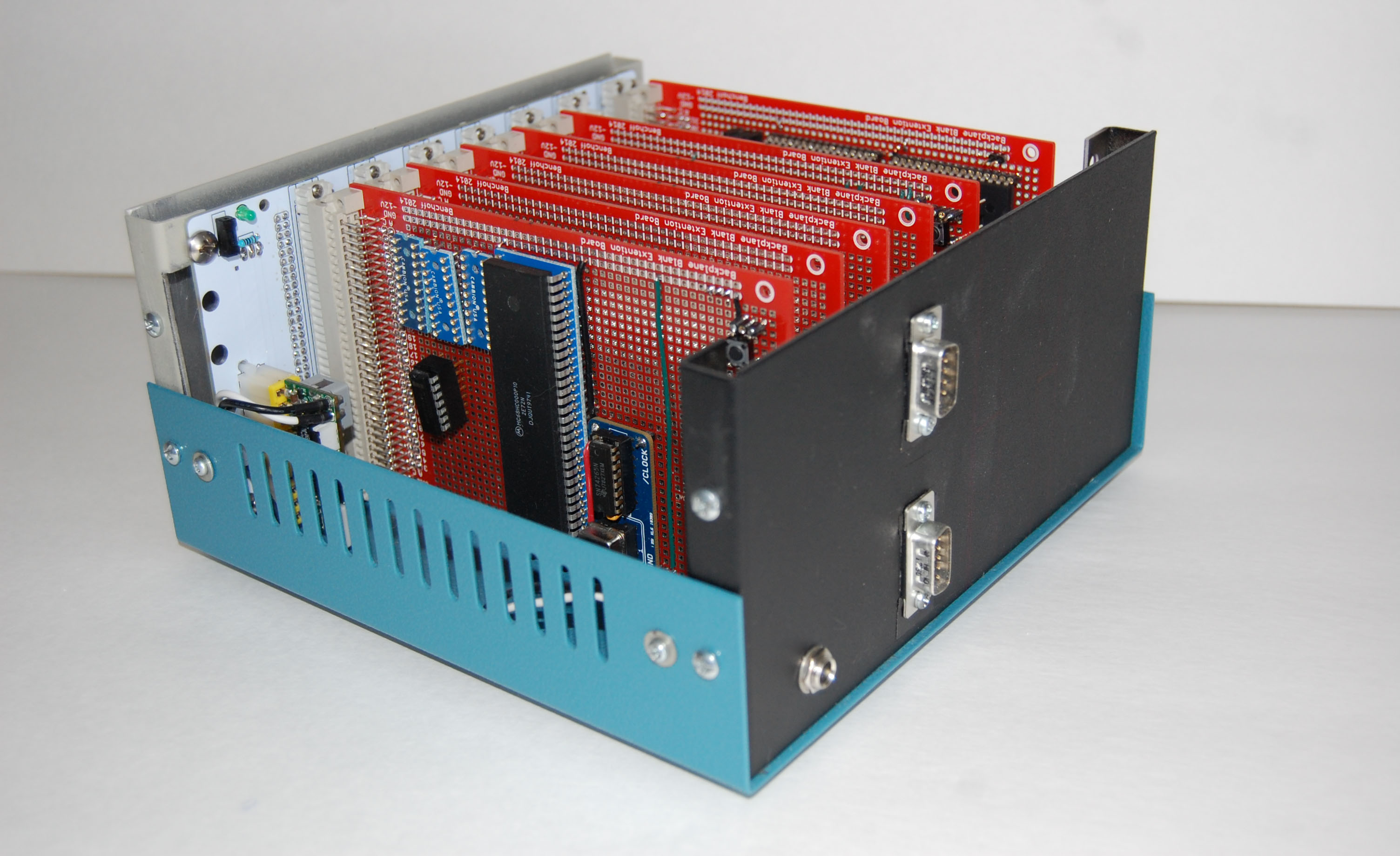
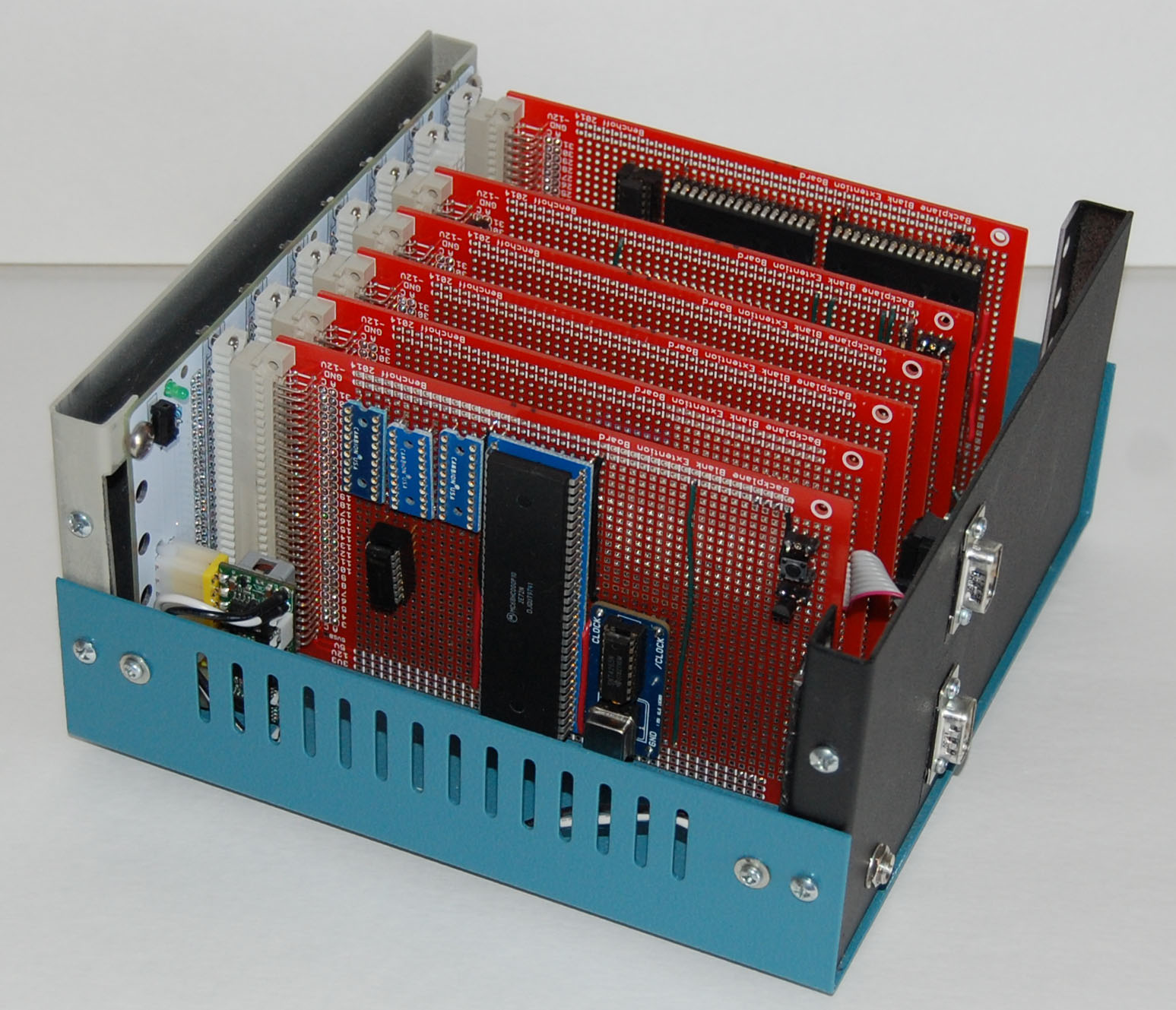
The enclosure I’ve picked out is a beautiful steel instrument enclosure from Hammond. Specifically, the 1458VD4B enclosure, measuring 8x8x4 inches. I love Hammond enclosures, and when I put the top on and screw everything together, it really looks like something from the early 80s.
The Power
In the world of backplanes and retrocomputers, power supplies are a bit of a problem. There are very old S-100 bus systems that used huge linear power supplies, with transformers and caps big enough to kill an elephant. That’s not something I want – or could even fit – in an eight-inch square case. Linear supplies are old tech, though. The Apple II and the Digital VT100 terminal – contemporaries of the 68000 – had switching power supplies, but unfortunately they were also huge.
A much better option for providing power to the backplane would be to take a normal PC power supply, add a 24-pin ATX header, and plug everything in. It’s a great idea, but even the smallest computer power supply would eat up a ton of volume in my enclosure.
Here is the solution. It’s called the picoPSU, and it’s barely larger than a standard 20-pin ATX power supply connector. It’ll provide 6A of 5V, and also has 12V, 3.3V, and -12V should I need that in the future. It’ll also power a hard drive, all without requiring any load. This is, by far, the easiest and cheapest way for me to power this computer.
The Backplane
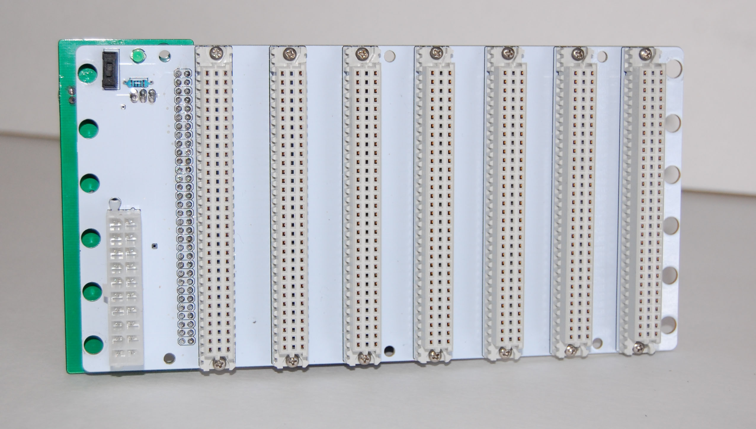
Now we come to the important part of this update. The backplane. The board I’m going to plug the CPU, ROM, RAM, Video, and Ethernet cards into. If the CPU is the brain of a computer, the backplane is the brainstem. If this doesn’t work, nothing will.
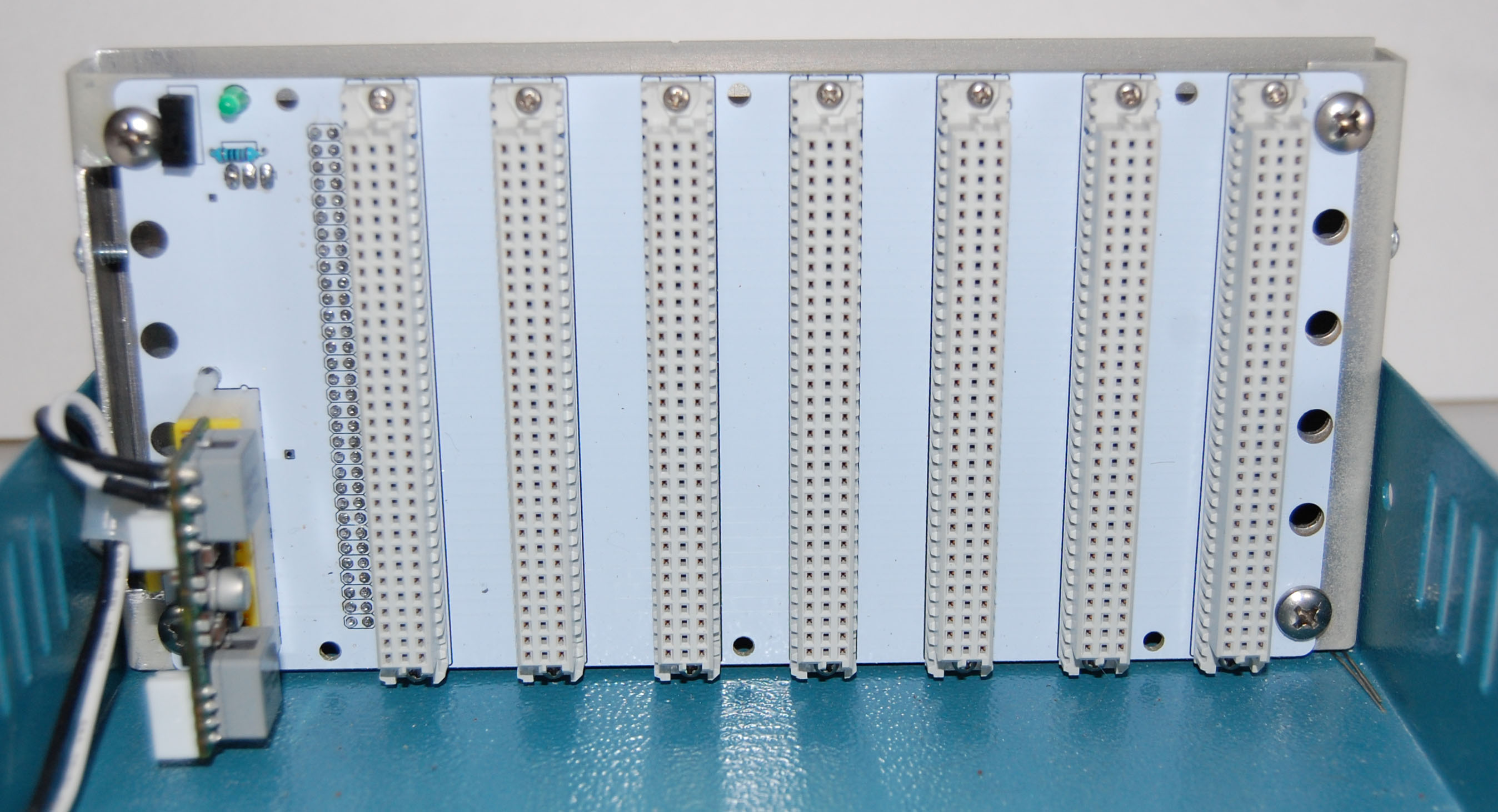 First things first. The backplane needs power. On the left, you’ll see a 20-pin ATX power supply plug, the picoPSU, a switch, and a LED. Care to make a guess what the switch and LED do?
Next up are seven Eurocard connectors. These are 64-pin Eurocard connectors, despite there being 96 pins. Only rows A and C (row B is the middle) have pins soldered to the backplane. There’s no logic here, just simple solder traces from one pin to another. If you’re extremely clever, you might be asking yourself why not use 96-pin sockets. I’m going to answer that with another question.
That’s the problem I faced when trying to design a two-layer 96-pin backplane. Why a two layer backplane? Because it’s cheaper. I’m also pretty sure it’s mathematically impossible. Proofs are welcome.
Either way, I don’t need 96 pins on this backplane. 64 pins are enough, once you know what you can safely ignore when designing something with the 68000. I’ll get to that in the next update.
With only seven card connectors, this isn’t a very large backplane. When you consider I’m doing the CPU on one card, RAM on another, ROM on a third, two more for Ethernet and video output, I don’t have much room to work with. From everything you’ve seen so far, there’s not even space for a cool ‘switches and blinkenlights’ front panel
But Wait, There’s More
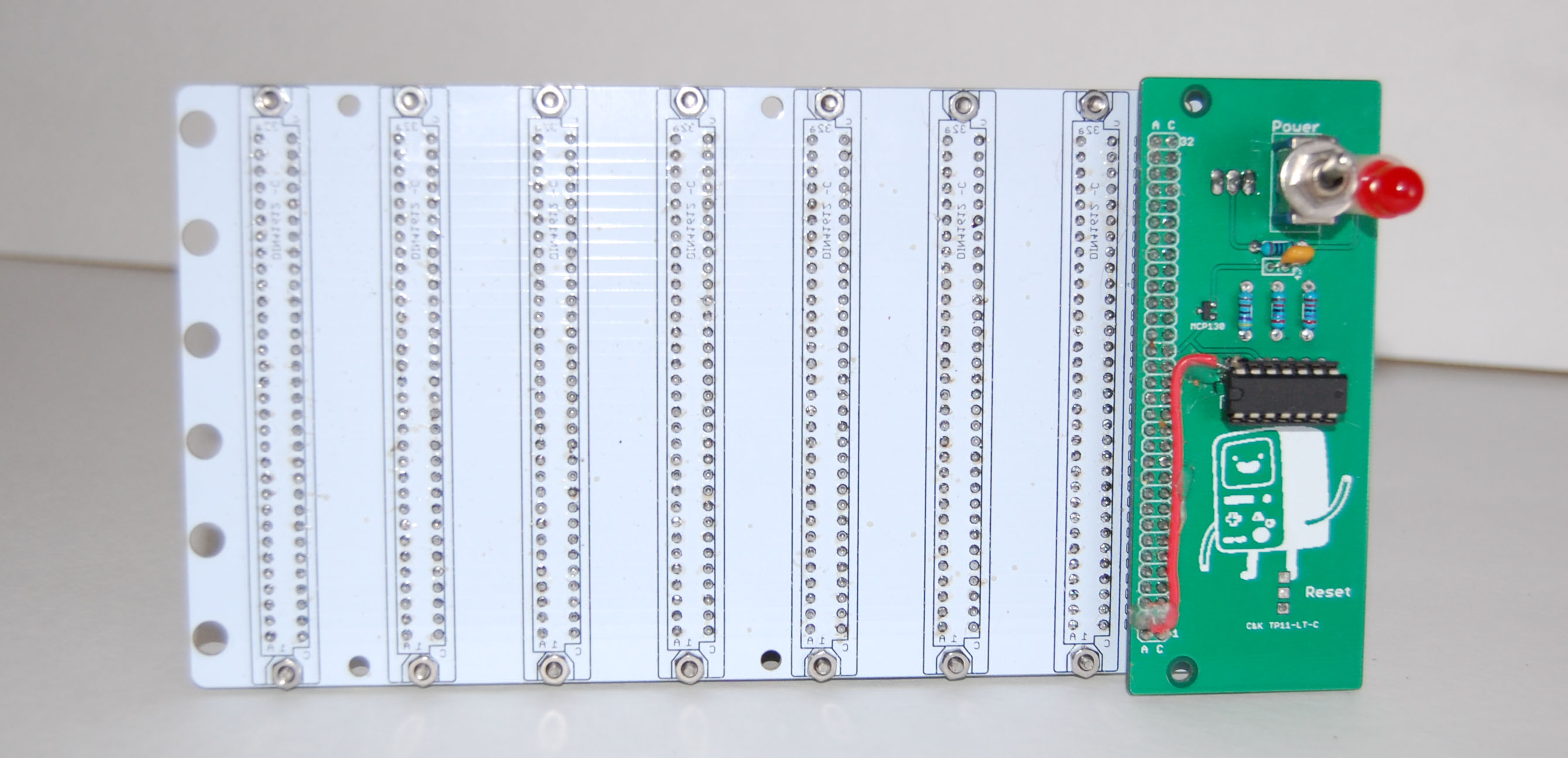 There’s the front and the back of the backplane showing off a neat little feature I snuck in. I call it a ‘frontplane’, but basically all it does is break out all the signals to a female 0.1″ header socket graciously supplied by Samtec‘s amazing sample request order form. They’re low-profile 0.1″ headers, meaning I can barely squeeze in an additional board between the backplane and the front panel of the enclosure.
What’s that green board, you ask? That’s my first attempt at making an external power switch, power LED, and reset button. Mechanically, this design did not work.The space between the backplane and the front panel of the enclosure is just too tight. This isn’t really a necessary part of the build – I have power and reset switches and buttons on the backplane and CPU board – but it does make it look nice. Right now, the ‘external’ controls for this project have been pushed back to the very end of this project. Or when I get stuck on something. I don’t know.
Other Electronic Considerations
In the first post for this project, a few people asked me how I would be terminating the backplane. Until I get the RAM and ROM working, I don’t know if I need to. I found this app note for RC terminator networks saying the 68000 usually doesn’t need termination on the data, address, or control busses. Don’t get me wrong, I’m going to be taking a scope to this when everything is wired up, but even if I do need termination, I’ll only need a few one dollar parts. It’ll also be a great use for the frontplane.
That’s All For Now
This is the most boring part of the project, I know. Still, it needed to be documented. The next update will more than make up for it. I’ll be going over the 68000 CPU itself, showing off what you can safely ignore, and telling you why designing a computer around the 68k isn’t much more difficult than designing a computer around the old 8-bit CPUs like the 6502. Really, there’s not much to it. Also, blinking LEDs. Yeah!
Here’s the link to the entire project on Hackaday Projects. Rate, comment and subscribe, or something like that.
And yeah, that’s a silkscreen of BMO.


Not only are double sided 96 pin Euro Card backplanes possible, you can buy them over the counter: http://ae.rsdelivers.com/product/vero-technologies/222-2470/96-96way-double-sided-eurocard-backplane/0435068.aspx
Oooohh…. That is a sexy piece of retro craft. The pic you sent me a while back was all out of focus. This one is drool worthy. Nice!
Try the routing in http://www.google.com/patents/EP0027047B2?cl=en on for size. Provided you can route narrow enough you get all 96 connected *and* ground segments between signals for the spaces between connectors. All in 2 layers (not counting jumpers to connect the ground segments)
I’ll be damned.
What he said. *goes to corner and cues up Monty Python theme* I swear I hate mathematical puzzles.
“I’m also pretty sure it’s mathematically impossible”
Any netlist can be routed in 2 layers, provided the signals/vias are small enough.
I downloaded the CPU board and schematics Eagle doesn’t like them for some reason. I’m getting a error line 7 column 6: This is not an EAGLE file.
This happening to anyone else?
Eagle 6.5 on windows 7 and XP same error on both systems
Thanks,
Bill
http://i.imgur.com/lbaH6uw.png
I didn’t do any of the red pins (I only used one layer for the green and blue), but you get the idea. This is a lot easier to do in eagle. You’ll have to look up your fab house’s tolerances and make sure you don’t exceed them, but it’s perfectly doable, especially if those are 0.1″ spaced. I’d do all the power on the layer with only 1 bus, unless you’re doubling up on pins for power.
The picoPSU is a DC-DC converter that requires 12VDC as input. Where are you getting the 12VDC from? Why not just use an externally mounted ATX power supply then?
It’s a ‘brick’ power supply, like a laptop. One wire, barrel jack, and it’s the same one I use for my lipo battery charger.
My htpc also uses a picopsu. those things are perfect! i’ve got a 12V power supply meant for powering kitchen lights@12V,10A inside my case, but my case is a lot bigger than yours!
I really like your project and hope to see more of it :)
Um, what does the output of that picoPSU look like on a scope? Tiny psu’s with few/small caps have a nasty habit of being noisy…
Adding a card with nothing but capacitors for supply filtering would be sad, but also kinda funny.
Someone made something kind of like that for PCIe:
http://ixbtlabs.com/articles3/monitor/his-iclear.html
It didn’t do much of anything.
Supply filtering needs to be done right at the end of the PSU, and/or right near the consumer. It’s mostly pointless to do it on a separate card, because of the added inductance.
would rather have one good switcher and some lambda power moules or something. going smd just seems so fake.
As old balkan proverb says, you seem to be working on offspring without functional penis.
You don’t really have all pieces of this puzzle but you are already building a prototype.
Don’t you think it’s to soon for this ? Your ideas are too rough to take them as they are and make something useful or even interesting. You should IMHO be still deep inside reading phase of your project.
Yeah maybe so. Do you have a proverb for the guy that reads books his whole life, then finds himself w/ wrinkles and balding head and hasn’t started building his computer? I think his penis won’t be functioning then either too.
I commend Brian for doing this in public b/c I sure as hell don’t want my project being publicized until I’m done as I know I will run into errors when I try to build a new design; I want a new style of computing. I’ve still got other knick knacks I want to do first, but I’ve got 2 designs that just need to be put together.
I don’t need exotic proverbs for George Bush “I’m a doer, not a thinker” approach.
It speaks for itself.
There is no substitute for real brainwork. Good things take work and time.
What if you learn by doing? And at a certain point the more info you read the more the older info slides out your gray-matter RAM; so you need to build some then move on.
Fine, but then iot should be labeled properly.
Then, it’s not a matter of “let’s do XY” but “let’s educate AB enough so that he can do XY”.
I might find joy in first, less so in second sort of a project.
Of course, I’m not judging, just saying that one should label his projects honestly.
This one amounts to OP poster waiting passively with 68000 in his hand for a crowd doing his thinking for him.
And IMO “going without penis into marriage” really describes him accurately.
He would like to be a designer it’s just that he can’t design or make a PCB worth a spit and won’t be bothered to learn.
He also seem intent to ignore everthing about physical realities, impedances, reflections, EMI etc and sees hardware desing as something one does on virtual server or prepackaged. Like unpackaging the server and code for his site for example.
Unpack your files, set a bunch of masks and CSSes, run the server and off you go.
I can see this project has written “stellar success” all over it…
Any plans yet re: the operating system for this thing? You might want to consider RetroBSD – http://retrobsd.org/wiki/doku.php
RetroBSD will theoretically run on 68000, but 68010 is plug compatible and a better choice if you want to run Unix. Old versions of System V will run on 68010. We used the 68010 as a multiuser system, it could handle three or four users editing and compiling C code from VT100 terminals. We used gosling emacs mostly but there were some vi weirdos. You could even run gnu emacs, but the other users suffered.
Since you’re using VME and 68000 which were made for each other, are you following the proper VME bus protocol?
What about the old Apple/TI NuBus? It also works with 68K and there are lots of interesting cards to play with.
VME protocol (with a few slight differences) == 68K bus protocol.
And for OS, 68K does not have an MMU, so you will need an older UNIX. Motorola had an OS for 68K systems…
Nice project, thanks for the flashbacks!
6A of 5V is not going to be sufficient to power this system if you are using 1980s memory technology. I’ve seen RAM boards from that era that use more than that all by themselves.
The box has zero airflow! Those slots are just a bad joke. 1980s technology chews quite a bit of power and gets toasty warm. Apple Mac had no fan, but they were very clever with airflow. This project is a fail without a case redesign for better heat dissipation.
How easy is it to install a fan? I’ve got loads of them I can send.
What’s the heatsink situation looking like too?
Sucking-out fan in the back, row of vertical slots along the bottom of the front panel should cool it fine, if the boards are aligned with their long axis front-to-back.
I’m using modern low power ram, so that’ll be drawing 280mA max. That’s half as much as the RAM chips in the Mac 512.
To my eternal shame perhaps, I distinctly remember putting an Altos ACS 68000 (http://en.wikipedia.org/wiki/Altos_Computer_Systems) in a skip.. (this was many yearsa ago,we were all much younger then).. It bore a remarkable architectural resemblance to what you are proposing building… and ran full blown Unix System III – and a “reasonable number” of Altos terminals (Wyse 50 or VT100 clones).
.. oh.. and it cost about £15,000 new, which is why it stuck in my mind when it hit the skip… (the general rule of thumb was if it cost $100 in the USA, it cost £100 in the UK, exchange rates didn’t seem to feature much in this particular equation).
Looking at the backplane PCB layout, I see that all the tracks are narrow, signal-type tracks. None of the tracks are thick power-type tracks. On many of the backplanes that I’ve seen from the 1980s, power was distributed by much wider tracks than the signals, with ground very often handled by a wide copper area all the way out to the edge of the PCB.
I’d suggest using a scheme where power is sent along wide tracks that cover both A and C rows of the connectors. This will reduce the power supply impedance and reduce the effect of current spikes (which can cause “ground bounce” and other problems).
Another trick… on some designs, heavy wire was solder bridged between several pins on each connector, so for example the last n pins of each connector A and C rows were bridged together and a big fat wire daisy chained on the backplane between each connector to provide enough copper thus avoiding flimsy easily fried tracks completely.
Not as tidy looking as neat PCB tracks, but much more robust, given the curruent (and thus heat) involved.
Somtimes this sort of thing was even added as a repair mod after the original tracks had lifted or burnt. Perhaps it is time to start working out how many amps this beast is going to eat on each supply line.
If you use a 4-layer PCB as the backplane (and I would recommend this), you can use the inner power and ground planes to distribute power to the sockets. The ground plane will also act to reduce noise on the backplane bus signals.
You could have purchased a blank 8 slot backplane from N8VEM:
http://n8vem-sbc.pbworks.com/w/browse/#view=ViewFolder¶m=ECB%20Backplane%208
They didn’t have any trouble routing all 96 pins.
19″ rackmount and that would be sexy
Okay fine. Its already sexy but I still want rackmount and maybe redundant PSUs.
Make that solar powered and with windmill to boot.
What if Skynet awakens ang goes against Khruschev and his counterattack vaporizes everyhing but Sarah Connor.
Who will keep that LED blinking during first wave of rebellion ?
;o)
BTW, since I can’t comment on your blog post about the prototyping card (“How to piss off a board house”), did you know that you can buy ready-made boards like that? Eurocard sized, with pads for a DIN 41612 connector, square solder pads all over. They’re made by Roth, part number e.g. RE201-LFDS, Farnell 117-2158, about ten quid each. Again, a common item in the 1980s before we had CAD and PCB houses that could accept files via E-mail!
I love this systems , I want one of this when it will be ready
Build one yourself. You’ll get a lot more satisfaction than simply flipping on a switch and playing with it for 5 minutes until you get bored and look for the next easy thing.
Actually, if you can have 6mil traces with 5mil spaces and 60mil annular rings for the through-holes, you can route it in a tidy, regular pattern on one layer. Been there, done that, when VMEbus was all the rage.
-65 ºC to +125 ºC Non-Operating. 1.75:1
Max. 10 BIT TTL.
I’d use the third row on the Eurocard connector for ground and power lines. Signal lines would be wired on one side of PCB and ground/power on another. Ground would occupy half as a groundplane then there would be 3V3, 5V and others….
Just my 2 cents….