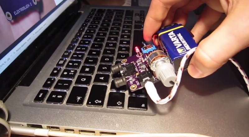
[Jonas] over at LOM Instruments is running an Indiegogo campaign for his newest creation, Elektrosluch 2. Like it’s predecessor, Elektrosluch 2 is a means to listen to the electromagnetic sounds of the world around you. Fans, computers, cell phones, routers, and just about anything electronic create strange and interesting sounds when probed with Elektrosluch 2. The campaign seems to be doing well enough with its target audience of experimental music and audio folks. However at €45 ($62.37) it’s a bit pricey for our blood. Unfortunately, [Jonas] hasn’t open sourced the project. All hope is not lost though, as Elektrosluch 2 appears to be simple enough that our astute readers should be able to build their own.
The concept is easy to understand: a coil of wire placed within a magnetic field will have an induced current proportional to the strength of the field. Electric Guitar pickups operate on the same basic principles. [Jonas] appears to be using two coils – probably tuned to different frequencies. We’re talking about relatively small magnetic fields here, so the signal will need to be amplified. In the Elektrosluch 2, the amplifier is an 8 pin SOIC which we can’t quite make the label out on. A few capacitors and resistors limit the bandwidth to audio frequencies.
[Alan Yates] created a similar circuit to diagnose dead Christmas lights. In [Alan’s] case, he used a pin instead of a coil. Two transistors and a handful of discrete components performed the amplification duties.
[Thanks Alexander!]


Back in the day, we did the same thing with an AM radio.
Back before that we had GDOs (Grid Dip Oscillators… would make for a great retro feature here on HAD).
When I saw the photo with the keyboard, I figured “Elecktrosluch” had to be an electric suction vacuum for cleaning keyboards and stuff.
If you can still find one, a telephone pickup coil will do it, as will an audio head out of an old tape recorder or VCR.
Am i reading this right? See idea on Indygogo, reverse engineer product, ask readers to make it. Bypass crowd funding. That’s what just happened, right?
By your logic, making any competing product is “wrong”. Competition is what keeps prices in check and offers choice.
The bit that irked me was the attempt to read what the IC was. Saying “Here’s a cool idea, here’s the principle, go build your own” is one thing. Attempting to actually rip off the specific parts used is another.
Either the part choice isn’t that important and the readers can decide for themselves, or it involved some research, perhaps some prototyping of alternatives, and by trying to publish the part you’re nicking their work.
Yeah, yeah, I know there’s a blurry line, but when the attitude is about copying rather than reinventing in your own way, I think it sucks.
There’s nothing new under the sun my friend. We’re all standing on the shoulders of giants. Take whats there, compare contrast and improve. That is what hacking is.
“They say great hacks are built on the shoulders of giants – not here. At Hack-A-Day we do all our hacks from scratch; no hand holding.”
As if the guy didn’t steal it from yet another source, let’s be real.
also, this is hackaday, and visiting is optional.
Yeah, I am that guy. And no, I didn’t steal it from anywhere, designed the circuit from scratch. Regards,
Jonas
Here’s the secret: “It’s an opamp”.
This, HAD, article just tells you to connect a coil to an amplifier to get a gadget to “hear” EM noise. None of that is a secret, or even anything anyone who knows any electronics at all wouldn’t already know. It’s not like it’s anything patentable. It’s obvious. So there’s nothing to give away.
There’s stuff you could do with beat frequencies to let it tune in to other frequencies, but since this thing’s just an 8-pin chip, it probably doesn’t do that.
This. The point of this article is not to undercut, steal, or re-sell [Jonas] design. In fact, he was already past his goal when he submitted the tip to us. The point is that it is a fun, simple circuit that anyone can build. If there is any secret sauce here, it is not in the Op-Amp choice, but in the filtering network.
For those who don’t want to RE their own product, build, and debug it – they can pay the extra ~$30.00. I don’t see this as a threat to any major crowd sourced funding project. Most people will pay for that convenience.
There’s a difference between talking about how to make a product and saying one is too expensive so were just going to rip it off. I feel like HAD just ripped off a member of the hacking community instead of giving back to it by supporting it. Again, talking about how to achieve the same result is one thing. Blatantly saying its too expensive screw you fellow maker is another. Why bother letting HAD see your kickstarter or indigogo any more?
The hacker mentality is all about making your own. You take your ideas from wherever you can get them, including others’ work.
I bet the IC is some op-amp. Would probably achieve similar results with a cmoy amp with lots of gain and inductors for the input.
In principle, at least, this seems a lot like the commonly available inductive amplifiers I’ve used for years when telecom work. They may be tuned to be a bit more selective than the hack at hand, but I doubt it. I’ve heard a whole lot of 60Hz hum and higher frequency computer noises with mine.
For example:
http://www.newark.com/tenma/72-8500/cable-locator-inductive-tone-probe/dp/80R7549?CMP=KNC-GPLA
Guitar pickup and preamp job done.
Yes, but not with the same audio quality (and not stereo).
I remember doing this with a telephone pickup coil designed for turning a handset into a speakerphone. It literally is just a coil hooked up to a microphone amplifier.
Incidentally, I’m fairly sure the two pickups are just to offer stereo sound. It’s not really a tuned circuit any more than a microphone is.
That would be possible; you would then be able to hear where the source is, by moving the thing around, and listening to the placement of the sound between both channels.
My first guess would be that he amplifies the difference between the two, either by feeding them into a differential amplifier or simply by connecting them in anti-series, to suppress fields at large distances, when the signal induced in both coils will be nearly identical, whereas fields from sources which are very close will tend to vary much more with distance, and therefor induce very different signal strength in one coil versus the other.
I think a controllable oscillator and downmixer would be nice, to be able to shift higher frequency signals into the audible range.
I do agree with some other posters that trying to rip off a gadget while someone is trying to get crowdfunding is rather uncool, even though the pricetag seems a bit steep for a small PCB with some common and not particularly expensive parts, although it does include a casing and seems to come assembled instead of being a kit.
It would have been nice if he would have offered a kit option, with or without the casing, as a lower cost option.
Hey, I explained the price in another post. Reposting it for you:
For those wondering about the price – it might seem a bit steep, but don’t forget few important details: one thing is making something on a protoboard at home and one thing actually designing a product. Take these things to consideration:
– research and development (PCB, components, casing, painting)
– gold plated, locally (slovakia) manufactured PCBs with non-green solder mask
– laser engraved and cut casing from plexiglass (not cheap), also done locally
– high quality components (Burr-Brown opamp, low impedance long lasting Panasonic electrolytic capacitors), soldering paste
– making sure you get the right quantity on time also sometimes costs a bit extra (ordering from different distributors)
– hand painting of the engraving with acrylic
– hand assembling with SMD reflow and regular soldering
– hand assembling the casing
All these things things cost money and my time (and I’d like to pay myself for the work, sorry if that makes you angry).
Regards,
Jonas
Well said. I designed a USB keyboard controller for old-fashioned IBM capacitive (pre Model M, pre Model F, the beamsprings) keyboards. I open-sourced the design, offer kits, but mostly people just want to buy the finished and assembled boards. Even with me making very little money on each one (I certainly don’t get much of an hourly wage for hand-soldering them!) the price very quickly goes up. It’s amazing how a handful of 50¢ 74-series logic and a microcontroller can bring a board up to $50.
Good luck with the manufacturing! I like the sunken paint in engraving idea.
I don’t believe that would work. Apart from both being close enough they’ll pick up similar signals, the signals from each would be out of phase, making it impossible to reliably cancel distant sources by taking the difference. If this were that easy, every microphone would be doing it. :)
Electromagnetic fields travel at the speed of light, so the phase shift from a distant source would be tiny. With a nearby source, the difference in field strength will net a signal.
It’s described as stereo on the Indiegogo site. The twinned sets of capacitors give the impression, too.
Anyway, he’s made his minimum money, so he can make his ‘sluch and lovers of wierd atonal noise-music everywhere can be satisfied.
I think this comes in handy in the repairworld.
some quick listening will let you know it works again
I’ts not exactly same but I’ve had a lot of fun listening to EM fileds with these:
http://www.techlib.com/electronics/VLFwhistle.htm
http://www.techlib.com/electronics/lightning.html
You can hear the wifi AP ticking. Each switched power source screams differently and if you connect large enough antenna you can listen to closest radio station.
Although I can no longer find the exact shematics I used for the build there. It has a diode right after the antenna and capactior.
Does this do more than a sensitive microphone with the sond on high? Basically if i got it right it turns not audible frequencies to audible ones..
I think it my be funny, but does not worth more than 5 bucks for me.
It doesn’t affect frequency; it translates EM radiation into sound. It’s effectively a microphone without the diaphragm, and a microphone amplifier.
Hello everyone,
I am the creator of the device. I would like to clear out some details about the project. I didn’t make the project open-source yet, since I didn’t manage to run KiCad on my operating system – and I don’t consider posting Eagle files online as open source, it should be done right – right? I don’t have any problems with people reverse engineering it, but know that the original schematic and board files are coming soon.
For those wondering about the price – it might seem a bit steep, but don’t forget few important details: one thing is making something on a protoboard at home and one thing actually designing a product. Take these things to consideration:
– research and development (PCB, components, casing, painting) – gold plated, locally (slovakia) manufactured PCBs with non-green solder mask
– laser engraved and cut casing from plexiglass (not cheap), also done locally – high quality components (Burr-Brown opamp, low impedance long lasting Panasonic electrolytic capacitors), soldering paste
– making sure you get the right quantity on time also sometimes costs a bit extra (ordering from different distributors) – hand painting of the engraving with acrylic – hand assembling with SMD reflow and regular soldering
– hand assembling the casing
All these things things cost money and my time (and I’d like to pay myself for the work, sorry if that makes you angry).
Also remember another part of the process – 45 euros includes shipping, packaging, paypal and indiegogo fees (which are not so small!). So yeah – I just wanted you all to know that.
And hey – hackaday – you could have choose a less attacking title. I love your articles and the work you’re doing.
Regards, Jonas
Thanks for coming by! For what it’s worth, a lot of OSHW projects design their stuff in Eagle, and post the schematics in Eagle format. I don’t think you have any obligation to convert them to Kicad, though if you want you could also provide the schematics in PDF form, and the gerbers.
^this
KiCAD may be the _true_ open-source option, but uploading schematics in PDF and the .sch/brd files will make 99% of the open-source community happy. The people who really care will go to the effort of importing the EAGLE files into KiCAD and be happy.
I wouldn’t back this project solely because I wouldn’t actually use it, but the lack of open-source is my only quibble I have with it (price seems perfectly reasonable to me)
By the way, if there is someone who’d like to help to convert my Eagle file to Kicad, send me an e-mail: zvukolom AT zvukolom.org
Now lets see one that cracks encryption by listening to em radiation instead of sound like this one does: http://hackaday.com/2013/12/20/ambient-computer-noise-leaks-your-encryption-keys/
Does anyone know if this would work and if it could be more efficient than the method using a microphone?
TEMPEST v2.0 maybe… but with a much more limited range.
I never post negative comments in general, but felt compelled here. This does feel a little wrong to me for an influential site like Hackaday. someone is trying to get something funded as a small indie campaign and then it gets broken down as an easy self build before the campaign completes, potentially damaging its chances (I’m sure that won’t happen, but it’s the principle).
That’s all. I’m very happy to see this type of breakdown happen in any other circumstance, including for my own posts and projects.
He hasn’t “invented” anything. If I want to sell dog turds with lolly-sticks in them, I shouldn’t be surprised if the local animal shelter decides to undercut me.
Of course not a unique invention.
My point was more that Hackaday is not the local animal shelter, they’re more of the fellow tinkerer… The champion of hacker ideas. I guess its a really thin line. Not trying to start a war.
Btw, your turds on lolly sticks comment got me laughing. :)
Cry me a river, but don’t tell us we have to bite our tongues. It’s what we do. Figure out how stuff works and improve on it, or find a way to build it with parts on hand.
We could just as easily do it with a product at adafruit or sparkfun. If someone has the time and energy to build those designs from scratch, make a board, whatever, they can knock themselves out.
“Cry me a river, but don’t tell us we have to bite our tongues.”
Thanks for telling us to bite our tongues.
“Figure out how stuff works and improve on it, or find a way to build it with parts on hand.”
Neither of which correlates with the tone of the post, which basically says “It’s too expensive” and “We tried to work out exactly which parts he used”.
However, Adam has clarified that what he was writing was a positive and constructive message, and the idea that it might be a suggestion to un-creatively rip off an expensive design was just a misreading.
Even better, the designer is opening his design. \o/
Well I guess you cheap skates don’t get that indiegogo isn’t about just buying things. It’s about helping people to do what they love and keep doing it. You shooting it down just makes you look jealous.
https://www.youtube.com/watch?v=qRasrZLdeEU
Original invention or not, crowdfunded, etc – whatever the debate here – I think this device (or some derivative of it), for the price, would be an interesting diagnostic tool to have and use for certain “blackbox” troubleshooting scenarios…
For instance, for about a week now I have been trying to help troubleshoot an issue for a friend who has an electric mobility scooter that won’t power on; we know that the basics are good: batteries, all connections, seat switch, power switch, motor, comms cable between the controller and the control panel, etc – we know all that works.
But the motor controller (so far) is a “black box” (it’s seems like its likely a potted device) – nothing seemingly available online about it (not even a connection diagram; the scooter is fairly old). Maybe a device like this could help us at least pin-point where the general failure is (we know it is likely the motor controller or the control panel), by being able to “listen” to its operation (or non-operation).
Anyhow – I could see something like this being useful for more than just “play” – at that point, the price might be justified as a product.
I was wondering the same thing. This really is interesting for debugging purpose. I imagine running motor PWM at 400Hz vs 20Khz. Hearing current peak or other things related to electric noise. I assume that if is sounds good, it might work good.
This seems a lot like using the probe of an oscilloscope as an antenna, optionally with a speaker on the output of the scope.
The version I made, back in the early 80’s used an MPF102 FET and an LM380 audio op-amp. The [Alan Yates] version is smaller, and uses less power. You could probably fit one in a matchbox, or a TicTac packet.
This reminds me of all the “C-Moy” headphone amplifiers, available in eBay. If you don’t have the time, tools, eyesight, or dexterity, why not buy one?
Well done on having a successful kickstarter campaign, It’s a nice looking project.
This is exactly the kind of project you would think HAD readers would enjoy but instead your all acting like a bunch of jaded ass holes.
Guys, he did opensource the hardware schematics, posting them to Github.
https://github.com/LOM-instruments/Elektrosluch-2/