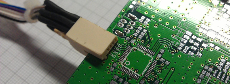
When [turingbirds] was looking around for the absolute minimum connector for a JTAG adapter, he wanted something small, that didn’t require expensive adapters, and that could easily and reliably connect a few JTAG pins to a programmer. This, unsurprisingly, is a problem that’s been solved many times over, but that doesn’t mean there isn’t room for improvement. [turingbirds] found his better solution by looking at some old card edge connectors.
Instead of 0.1″ pitch pin headers, weirder and more expensive connectors, the Tag Connect, or even pogo pins, [turingbirds] came up with a JTAG adapter that required no additional parts, had a small footprint, and could be constructed out of trash usually found behind any busy hackerspace or garage. The connector is based on the venerable PCI connector, chopped up with a Dremel and soldered to a JTAG or ISP programmer.
This is simply a card edge connector, something the younglings seem to have forgotten. Back in the day, card edge connectors were a great way to connect peripherals, ports, and anything else to the outside world. They were keyed, and you could only put them in one way. They were relatively cheap, and with a big coil of ribbon cable, you could make custom adapters easily. For low-speed connections that will only be used a few times, it’s very hard to beat a card edge connector.
Of course the connector itself is only half of the actual build. To turn a chopped up PCI connector into a JTAG adapter, [turingbirds] made footprint and part files for his favorite PCB design tool. In this case it’s Eagle, and the libraries that will plop one of these connectors down are available on GitHub.
Is this the latest and greatest way to plug a programmer into a board? No, because this has been around for 30 or 40 years. It does, however, put a programming port on a PCB with zero dollars in components, a minimum of board footprint, and uses parts that can be salvaged from any pile of old computers.


Me gusta. I’ve been using a pogo pin footprint for a while now for AVR programming, but I can see how JTAG would do much better with a connector that stays on without being held in place.
I use cone tip pogo pins and made an ISP footprint that has centering holes in the pads. https://www.flickr.com/photos/macetech/18320439583
For mine, I only have the two center pads have holes. This saves a lot of space – you can route under a lot more of it on the other side, and I find that two holes are usually enough to position it well enough to program it.
I forgot to mention that I usually put this below a TQFP and the vias in each pad are fine because the signals needed to get to the other side of the board anyway. Like so: http://i.imgur.com/ibbaA9v.jpg
OK so that’s not the best example, but I’m sure I found an angle before that let me route most of the ISP signals underneath the chip :)
Those are some dope glasses bro!
Yeah holy fuck those are awesome!
I thought so too – got a set for my brother in law for xmas. Crazy bright – ‘aviation hazard’ kinda bright :-) Highly reccomended.
Check link for Tag Connect in article. It stays in place as it has retaining clips.
Those are ridiculously expensive.
I disagree, they’re priced very well. I’ve got the No-Legs cable for ARM SWD, and it’s a thing of beauty. 34USD is a no-brainer, given that keyed SMT connectors cost a couple of bucks each and take up more room.
http://www.digikey.com/product-detail/en/FTSH-105-01-F-DV-K/SAM8796-ND/2649974
35 bucks is not cheap, but you buy such things once and use it for years so I don’t think they are very expensive considering how they make job easier.
$35 is amazingly cheap for volume production! 100 mil pin headers are too darn big for modern stuff (card edge connectors aren’t an option either), and 50mil samtec headers (2×3 pins or bigger, FTSH or the like) are over $1 per board, in quantities of a few thousand. Tag connect saves that $1+ per board (times many thousand boards), plus the need to buy/ship/solder/rework/whatever the said connector. You save *everywhere*. It’s one less part to load in the pick and place, one less connector to mask for comformal coating, one less part part to worry about lead times or discontinuation, etc. It’s also smaller and it works better. There’s a good reason we use it, as do many other big players (I just noticed yesterday that TI uses it on launchpads)
The TagConnect is such a crap product. I have received multiple bad ones and the one-man0business refuses to listen to his customers. Rude and just plain unhelpful. Blamed it on me even though I have 50+ TagConnects. I have banned them from my company now :-) This looks like a great alternative.
this much be a case of “because you can”, it just as big as the footprint for a regular pin header (with staggered holes or bend pin you don’t have to solder it in) and most PCI connectors are rated for an surprisingly small number of insertion cycles, like 25-50
I put a card edge contacts on a design we manufacture. The $10 card edge connector has programmed about 2500 devices so far and shows no signs of wearing out.
It’s a matter of new gold vs old gold. If you are mating a connector with a _fresh_ connector the life is much higher than if you are mating the same two connectors. The fresh connector brings some new gold to the mix and keeps the old connector working.
> just as big as the footprint for a regular pin header
No it’s not, it can be used on a single sided board if you want, has no drills needed, and is designed to never need a part placed even ‘optionally’.
The only main downside I see is the routed slot for alignment, though you could maybe stick it on the edge of a square board if you aren’t worried about it going sideways on you.
This type of connection was probably abandoned because when board is in some case you don’t have enough space between board edge and plastic/metal case to connect this type of connector. If you’re working with a prototype board without case then sure, you can use this without problems.
Quite a few 1980s computers used a card-edge connector for adding peripherals. Can’t beat the price! Obviously the PCB part is on the computer itself. For a port where only a minority of customers are going to connect something to it, it makes a lot of sense, saving on 3 or 4 connectors on millions of computers each.
Downside is reliability. But you can’t beat that price!
In a Roomba almost all components (wheels, brushes) are connected with such a connector.
It must be an off the shelf connector for any number of pins.
nice
Agreed
It would be good form to make the ground pin/pad a bit longer to make it first-make, last-break. Even better to bookend with the longer ground pins, a la PCMCIA.
i have used this for years for a $0 cost to add jtag and swd and whatnot to things … super reliable and a nice connection and plenty of mating connectors on the market for this and even some with locking
its great on the bear board but once you stick it in a product it can be a pain
It worked great for the ZX-81, Vic-20 expansion cartridges, and untold numbers of other devices. Design the enclosure to accommodate it and it’s a feature.
None of which were gold plated so “worked great” is actually a completely inaccurate description. I recently soldered 0.1″ headers to the edge connectors on my Amstrad because I was fed up with them…
Yup. Rapidly oxidising connector since it was unplated together with a connector that had no mechanical support meant frequent random crashes/glitches because of a poor connection. It was an awful expansion pack system and only existed because it was dirt cheap to manufacture. It wasn’t reliable at all.
I have a CPC6128 and it has tinned 0.1″ edge connectors and they have corroded over time.
I tried to find a tinning solution to re-tin them but I could only find expensive “immersion” solutions.
I then thought of using a silvering paste that can be done with a cotton bud but silver oxidizes quickly. Fortunately silver oxide is not too bad a conductor but it might not be quite enough conductivity.
It irks me to change the connector away from original but I have been considering it as it would be so easy to solder duel row pin headers on and the edge connectors are $20 now.
Now I am wondering if I can just use some solder wick and solder and if I do, will it no longer be an option to use silver?
Any suggestions?
As much as it irks me, I *am* also considering pin headers.
Silver will be fine, one of the reasons it is used for relay contacts is because of the conductivity of silver oxide.
Thanks, I will give that a go.
The C64 used it for the user port and tape drive port, the cartridge port was an “inverted” design with the connector on the motherboard and the edge connector on the cartridge.
AFAIK the Enterprise 64/128 used edge connectors for everything in order to save some $$$. At least the C64 used real DB9 connectors for the joystick ports…
Why hasn’t anyone suggested custom made RJ45 cables.
He can arrange the cat5 wires whatever way he likes in the RJ45 plug and fit them to anything he can think of on the other side.. Plus the cable making tool is worth a few bucks at best
Needing to add a RJ45 socket to each board to program it defeats the no additional parts benefit.
yeah sure, not parts is better. but I prefer RJ45 smt-style for many reasons. the first being that they can withstand a good amount of abuse, are easy to replace/shorten/extend. I’ve attached sensors and other stuff to industrial machines just by making my own layout and sticking it on the machine(sticker) so anyone can service it. it sure beats screw terminals in terms of reliability.. that was on the machine at first. also, I’m very wary of custom work when meaning to create something robust.. I buy 16 8-pin clips for 1 dollar.
but honestly this post is pretty creative.. especially if we can find the parts on mouser for cheap.
I personally think, that with care, such an idea works well. I’ve seen some MAME arcade cabinets use them for interchangeable control panels.
The caveat is when some dipshit mixes multiple uses with the same connector in a machine. IIRC, there was a board here on HaD a while back that featured the same connectors but with different I/O. Worse, it was on the same side of the board.
So if you’re using RJ45 for your networking, probably not a good idea to reuse the RJ45 for anything else on the same board.
Why low-speed ? I use some for impedance controlled 165 MHz sine, the not-changing-planes actually has a nice ring (haha!) to me.
Molex makes a whole line of low profile fine pitch FPC/FFC connectors that are 50cents or so each in small quantities.
The catch is that the plain FPC cables that Molex makes get obsoleted every 6-8 months, so supply can be a pain.
I really like this idea, however I prefer using a PCB connector that can be bought instead of hacked like this one.
Any ideas for a ready to buy <10 pins small pcb connector?
http://www.digikey.ca/product-detail/en/7-5530843-7/A101966-ND/2310829
Manufacturer:TE Connectivity AMP Connectors
Manufacturer Part Number: 7-5530843-7
Description: CONN SEC II 3 POS 100C/L (6 pins 0.1″ pitch)
thanks. a bit expensive to my taste though
Hackaday is full of the cheapest people ever. $2.60 is too expensive for one connector you’ll use over and over? Are you plucking the rest of your components from the resistor and capacitor trees in your orchard?
Only the resistor and caps.. The others I harvast from crashed satelites in my backyard.
@[Sjaak]
Got any spare ICBMs out in the back yard as well??
Next time state your price and not waste my time.
Good off-the-shelf option, thanks for the link.
I wouldn’t use it anywhere that an unaware user might run across it, since it would be confusing and potentially harmful; but what about SATA? 7 pins, connectors and cables built for the demands of a 6Gb/s data link are available for peanuts, the cables virtually anywhere, the connectors under a dollar in quantity 1, scroungeable from dead HDDs if you are really hard up.
It is also only single-sided; but the size looks about right for use as an impromptu edge-connector(possibly with a plastic shim glued on to the other side of the board to match the keying on the cable) if you don’t want to deal with an actual SATA connector. SATA Power is also not one I’d use where somebody might get the wrong idea; but it is similarly close to being edge-connector height, and offers 15 contacts.
If you really don’t need that many pins, check out cheap flash drives for inspiration: those have largely switched from using ‘real’ USB connectors to using PCB edge connectors with just enough plastic around them to get a decent fit. Only 4 pins; but the price is right and you can duplicate the effect with just 4 pads and possibly a plastic shim, depending on your PCB thickness.
I prefer a zero cost small footprint and not something to mount on a pcb (and thus adding costs :))
As you stated users will think it is sata/usb and connect the pcb to a sata or USB port. I would try to prevent that ;)
I would try to PCIe x1 wasn’t used for this. There is a plastic wall between the 2×11 and 2×7 contacts segment. You can cut off the 2×11 side. You are left with a short connector that have 4 walls of plastic for support. Yes, you’ll need slots on the PCB.
As it happens, the PCI connector includes JTAG(optionally, not always implemented and almost certainly not usefully documented in any way whatsoever by your motherboard vendor) Pins 1-4(8 contacts, since the connector is double-sided) are reserved for the purpose.
Reading all the comments, I am a bit surprised at the reactions.
Good on [turingbirds] for putting this to use and hacking down a scrap connector… but this is a method that has been done for AGES in production boards. Quite often test pins on pannelized boards are brought out from all the individual boards to one edge connector on the frame of the panel. The whole panel plugs into the test stand and bam; test 6 products at once.
A few Dave Jones videos covers the method in detail. But yeah.. this is VERY VERY common in production work.. and all the “what about X” and “Why not Y” … its a solved issue. For all of the reasons stated in the comments: It costs NOTHING to implement on the board side, other than a few square cm of board space. I OFTEN see them crammed in not only on the edge of a panel but the individual boards themselves. And up against the inside edge of a case. Its not about “oh well you cant plug into it when everything is assembled so they just dont do it anymore”.. No.. the programming/debugging/test/calibrations are all done BEFORE mounting in the case.
Its the cheapest, simplest, most “zero parts” method of adding a production port. The only real disadvantage is that you are limited in PCB thickness options as defined by the connector spec.
And the yes, the PCIe 1x connector is becoming the common use connector for it. Another option if you only need a few pins is the USB edge.
Hmm. After reading all the comments I still think 0.100″ pin header is way to go for me. I only do hobby boards, so cost of headers is not an issue. Vias under TQFP and pogo pins is great idea, but needs something to hold them in place. PCI at card edge requires that cut with quite small tolerances(or maybe you could put that on corner of board) Anyways, too much small tolerances for home cooked boards?
After the PCB or pads wear you can just throw the board away…
Is it just me, or does this scream for an Atmel ISP programmer system? The six pins are superjunky, normally.
In my last design with PIC micro ICSP pins were used by circuit, so to be able to program in circuit I added three jumpers to MCRL, ICSPDAT and ICSPCLK lines. Whenever I need to change firmware, I remove jumpers and connect my programmer to exposed pins.
I have a broken HDD that uses two rows of small pads and two small holes on the PCB and custom-made looking connector with bouncy on the drive case for connecting heads and servo to the board. It provides 18 contacts on the area barely bigger than SOIC-16 package. Similar setup with four bigger contacts connects board to BLDC motor. Take something like ths, or maybe a SIM card connector, solder it to a piece of PCB, solder wires for your programmer and glue everything to a clothespin or some other clip. Then just place proper set of pads on your board, maybe with a pilot hole or some markings. It’s simple, it’s cheap, it’s a hack, so everyone should use it…
Edge connectors worked quite well when they were originally used in dust free environments.
An edge connect is wiping type of contact rather than a simple pressure contact. That is – moving or inserting the edge connector clears away a path through any oxidization on the PCB connector.
Because of it’s design – it is prone to failure when it is used a dusty environment where vibration or thermal cycling will cause dust to lift the spring contacts away from the PCB.
So they were only just alright in early home computers as it was not hard to remove and re-insert them when problems arose from dust in the environment.
Then when IBM started using them *inside* the PC-Junior and XT where they were not accessible, they started to fail often as the PSU fan tended to suck dust into the case and the user wasn’t able to give the connector a little wiggle.
Edge connector were then removed from FDD and HDD connections and replaced with pins. The other edge connectors on the main board were modified a little and the whole PC place on one side in the *tower* configuration so that the main board connectors were less susceptible to dust.
So this use of an edge connector is about the best place to use them.