[Hans] wanted to see the frequency response of a bandpass filter but didn’t have a lot of test equipment. Using an RTL-SDR dongle, some software and a quickly made noise generator, he still managed to get a rough idea of the filter’s characteristics.
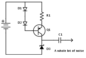
How did he do it? He ‘simply’ measured his noise generator frequency characteristics with and without the bandpass filter connected to its output and then subtracted one curve with the other. As you can see in the diagram above, the noise generator is based around a zener diode operating at the reverse breakdown voltage. DC blocking is then done with a simple capacitor.
Given that a standard RTL-SDR dongle can only sample a 2-3MHz wide spectrum gap at a time, [Hans] used rtlsdr-scanner to sweep his region of interest. In his write-up, he also did a great job at describing the limitations of such an approach: for example, the dynamic range of the ADC is only 48dB.


