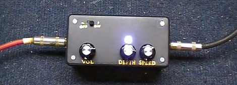
There’s a lot of builders around whose first foray in electron manipulation was building effects pedals for guitars. It looks like [Dino] might be getting back to his roots with his tremolo effects box how-to.
Last week, [Dino] found an old 5-watt tube amp in someone’s trash and decided to bring it back to a functional state. With his new trem effect, it looks like [Dino] might be getting the band back together.
Apart from tiny boost circuits, a tremolo is generally the simplest effect pedal you can make. All you’ll need to do is vary the amplitude of the guitar’s signal at regular intervals. After that, it’s only a matter of pretending you’re playing through a rotating Leslie speaker.
To get his trem working, [Dino] set up a 555 circuit to flash a LED at regular intervals. This LED is encased in heat-shrink tubing along with a photocell. This setup controls an LM386 amplifier. The build is really simple, but from the video after the break we can tell it sounds great.
[youtube=http://www.youtube.com/watch?feature=player_embedded&v=NHu0szLyr9U&w=470]


I must say I find the circuit peculiar; the input of the opamp is not shifted to half the supply, which probably clips most negative signals.
Also, the high-impedance output of the guitar is used without buffering, thus making the impedance of the guitar element part of the filter characteristics. Not necessarily bad, but good to realize.
Also, I’d like to shut off the battery completely.
The good part is that it works :)
With most other opamps you need to bias the input, but the LM386 has an internal 1/2VCC reference.
That 1/2VCC reference is quite useful.
The photocell seems a bit silly… I mean the solution is brilliant, but using a light source and photocell in this context… it just seems a bit odd.
No more than a spring reverb, with electromechanical transducers and a real honest spring.
I imagine that the really slow response time of the LDR adds character to the sound you wouldn’t get with a higher speed switch. That and you can find all the parts for the coupler in a dollar store nightlight.
It’s how they were done in the past before FETs became cheap and is still a valid solution, much better than a photodiode optocoupler. A LDR is a linear component while a photodiode is not, therefore you can let you signal pass through the LDR and control the flow using light without adding any distortion.
This schematic is badly designed and overkill for other reasons, but the LDR adoption is fine.
lol I’m an admitted hack, not a trained EE, but as stated, it works.
What makes a FET different from a NPN transistor or a MOSFET?
The 555 can drive directly a LED (it can drive small relays too!), therefore the transistor buffer is unnecessary. Also, the 386 is certainly not the best choice as a preamplifier, being a low quality and noisy power amplifier.
I would eliminate the 386 and the unnecessary 1000uF capacitor, drive the LED directly from the 555 then use the transistor as a common emitter preamplifier, fed by a voltage divider where the LDR is one of the resistors.
A bit complicated in written words, but much simpler in practice.
Cool! You should do that! :)
A useful trick with the 555 is that you don’t need the NPN inverter for the LED – if you put the LED between Pin 3 and ground, it fires when Pin 3 is high, and if you put it between Pin 3 and Vcc, it fires when Pin 3 is low. I’ve used that to make two-LED blinky light things with one 555.
Tremolo is not the same effect as a Leslie rotating speaker.
No one actually said the tremolo is the same effect as the rotating speaker.
Call this a phaser is a little much–none of the wet signal is delayed/mixed with the dry.
Using an LDR is tried-and-true here. Just look at the uni-vibe (and tons of amplifier tremolo stages).
PEOPLE! Stop using that huge (220uF) coupling capacitor with the LM386 output, when it’s configured as a stompbox. That’s the standard when driving a low-impedance load like a speaker. Just do the RC high-pass filter calculation for a speaker, vs. the calc for a high input impedance load, like an amplifier…
I enjoyed this. I don’t quite understand why he used a 386 to bring the volume back up when he could have used just a single transistor boost. Seems like the battery wouldn’t last too long powering both the 386 and 555.
It does sound pretty good though, and the use of a wet/dry mix knob to control the tremolo “depth” is clever. Many tremolo circuits that use 555’s have noise/ticking issues, and I didn’t hear any with this one.
That’s why I have a 1000uF cap across the power rail… to “mostly” eliminate that ticking. :)
He could use a TL072 with some bias as an output buffer.
RGB LED, vary effect.
to see world top heacker groups hit the below link
and much more about hacking
http://studentz.do.am/blog/hacker_groups_of_the_world/2011-11-30-1
I “m having trouble with a clicking noise. I don’t know how to get rid off it, and also the wet signal isn’t that “strong”, the phase/tremolo is difficult to distinguish.