The popularization of FPGAs for the hobbyist market means a lot more than custom LED controllers and clones of classic computer systems. FPGAs are also a great tool to experiment with computer architecture, creating new, weird, CPUs that don’t abide by the conventions the industry has used for 40 years. [Victor] is designing a new CPU that challenges the conventions of how to access different memory locations, and in the process even came up with a bit of example code that runs on an ARM microcontroller.
Most of the time, the machine code running on your desktop or laptop isn’t that interesting; it’s just long strings of instructions to be processed linearly. The magic of a computer comes through comparisons, an if statement or a jump in code, where the CPU can run one of two pieces of code, depending on a value in a register. There is the problem of reach, though: if a piece of code makes a direct call to another piece of code, the address of the new code must fit within an instruction. On an ARM processor, only 24 bits are available to encode the address, meaning a jump in code can only go 16 MB on either side of its call. Going any further requires more instructions, and the performance hit that comes along with that.
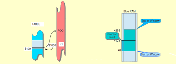
[Victor] decided a solution to this problem would be to create a bit of circuitry that would be a sliding window to store address locations. Instead of storing the literal address for jumps in code, every branch in the code is stored as a location relative to whatever is in the program counter. The result is an easy way to JMP to code very far away in memory, with less of a performance hit.
There’s an implementation for this sliding window token thing [Victor] whipped up for NXP’s ARM Cortex M3 microprocessor, and he’ll be working on an implementation of this concept in a new CPU over on his git.


Isn’t that how AVRs work? IIRC, the branching instructions can go 64 locations up or down from the current PC.
http://css.csail.mit.edu/6.858/2012/readings/i386/JMP.htm
x86 JMPs opcode EB and E9 are relative jumps too.
The HAD summary is very confusing. There’s a lookup table with 32 bit target address, and this lookup table uses index values based on an 8-bit value in the program, and the value of the Program Counter. So, the PC defines a certain window in the table, and you use the 8 bit index to select a value.
So he’s invented CISC indirect addressing?
The description here at hackaday is wrong. The jump is made indirectly, but the index addresses a location in a sliding window. The window slides as a function of the PC, but in an entirely different memory space.
Indirect addressing is standard on all CPUS i know, including the 6502. Am I missing something? Otherwise the “sliding memory window” is something that is supported by the MMU in modern (after 1990) CPUs.
Again, this is not an indirect jump/call. There is no support for this on any processor I’ve seen.
It’s basically a constant pool of jump targets. Why not just use it as a constant pool of 32 bit values, which can be used either as addresses, or as any other 32 bit constant ?
It also needs a better escape mechanism for when the constant pool is full.
Arlet, you are right. It is a bit like the constant pool, but better since it can be shared across multiple functions.
When the window is full you can always jump to another place in memory. The compiler can see that the window is close to being full and put some padding (or insert some data) before the function to create room in the table. In my forth work this happened pretty rarely.
Thank you for your great 6502 core, BTW.
Is this already possible to some extent by adding an immediate value to the PC? (Though this only gives four bits of resolution plus some shifting.)
I realise that if someone’s gone to the trouble of modifying a processor instruction set, they’re going to know it pretty well and if there’s already a workable variant they’re not going to bother reinventing the wheel.
The point of this exercise is to move the references to some other place where they can easily be found and shared across different routines. PC-relative addressing does help.
http://infocenter.arm.com/help/index.jsp?topic=/com.arm.doc.dui0489c/Cihjffga.html
again, PC-relative addressing is not helpful. ARM does not support
[BASE + ((PC>>4)*4)]
If it did, I wouldn’t be doing all this FPGA work…:)
Sounds familiar somehow.
First thing that it brought to mind was this ..
http://www.cs.utah.edu/~elb/folklore/mel.html
Thanks for posting that! I really enjoyed it!
Along the same lines, another oldie but goodie
http://www.pbm.com/~lindahl/real.programmers.html
Sorry, ignore my above post, originally I completely misunderstood what he was doing.
Sounds a lot like the National Semiconductor SC/MP of the late ’70s. Relative addressing based off the program counter.
Please read the article. hackaday described the jump system incorrectly
This also brings to my mind the PC-relative addressing that exists on many processors, but probably was popularized by the Motorola 6809.
Nothing against doing something just for the practice, but it’d be nice to see some actual analysis of the problem, and how this solution will help. Eg. have a simulated processor run some realistic code not specifically engineered to showcase far jumps, with performance measurements. Also lacking is details of how this will affect the CPU pipeline, and how compilers can take advantage of this feature.
Thanks for your comment.
Any reasonable application that is factored well is a showcase for calls.
Another article will address compilation in greater detail.
loading registers including the PC (aka a jump) from an address at an offset
from the current PC is exactly how an ARM does it, look up LDR and its cousins
Except that this design uses a separate memory space for the constants, while the ARM just reads them from program memory.
Relative jumps are old and nothing of a new thing.
This is not a relative jump.
Sounds a lot like how the TI-99/4 and 4A operated. “Only the Program Counter, Status Register, and Workspace Pointer registers were on the chip; all work registers were kept in RAM at an address indicated by the Workspace Pointer. 16 registers were available at any given time, and a context switch instruction which changed to another workspace automatically allowed fast context switches compared to other processors which may have had to store and restore the registers.”
Imagine that concept running on a current speed CPU, with many more workspace pointers and much larger workspaces.
There’s an even better way – keep those registers with you.
Heavily pipeline, but make the pipe wide enough to carry the instruction, PC and “registers” (operands/result/src/destination addresses) along in one cycle, then just switch to the next thread every clock.
It means that one thread takes ~ 100 clks per “instruction cycle”- to and from memory a couple of times, via operation units, in lots of little steps. All the “registers” are in memory somewhere, apart from the specialized units used as fifos or rendevous between threads. (or to initiate a run of subthreads, or to collate results).
The reason the very next clock can’t be operating on the same thread is because such pipelining causes hazards – the “instruction” hasn’t actually completed yet!
But then you get to run up to n threads concurrently without impacting any threads performance. (if the round trip for one “instruction” worth of thread – from one instruction fetch to the next in the same thread – was n clks.)
This also makes time management easier, as you can easily calculate how long a thread will take to execute, regardless of what else is running. (once you know the map of the specific layout, at least).
Add a way of “holding” low priority threads in a round-robin manner, and you can have any number of user threads at uncertain speed, plus a few “real-time” system threads doing time-critical IO type tasks.
One would then swap having a “ALU” that can *optionally* perform different operations, for a bank of dedicated adders/multipliers, fifos/semaphores etc. This way the “opcode” becomes in effect an address used to route the “instruction” in flight. This means extending the architecture is really easy as well, since a given packet doesn’t need to execute always in the same operational unit – it carries its payload/operands with itself anyway, in parallel.
One could also conceive of reconfiguring a block of operational units to change the number/type of such dynamically, on an as-needed basis. If the adders are running flat out but some of the extra multipliers are stalled, reconfigure the excess multipliers as more adders.
It should achieve much better performance/watt overall, at the cost of not running any one thread particularly fast, by modern standards. If many op units aren’t needed, power them off. The idea is to contruct the architecture from the “worker’s” point of view, IE: keep the op units busy! This is in contrast to conventional design, which is to make one thread go as fast as possible, then try to extend to many. Better would be to make any “high priority” thread *always* execute in the same time, regardless of whatever else is happening, then to allow many other things to happen so as to use up all the op unit’s schedules.
It’s a bit of a stretch to call such a thing a CPU though, since it’s the opposite of a central processing unit – more a decentralized computation grid. (or maybe, substrate?)
All the above is free for whoever to try their hand at it – I have been “putting off” sitting down with an FPGA to implement this for about three years now. I am well familiar with the “character building” nature of detailed computer engineering. The article is spot on about that!
For all I know, all those threads in flight will encounter sticky “traffic jam” issues.
That or the whole width will end up just too wide. But I suppose it doesn’t necessarily have to have every part bit of the width in the same place – so long as the path takes the right number of clocks to get to where it needs to.
Anyway, an interesting paradigm flip which may or may not help. It’s interesting, however, that modern supercomputer architecture chips do exactly this sort of ‘fine grained’ SMT – usually across their fairly shot pipelines.
Remy – It seems like you are mostly describing a hyper-threaded CPU:
http://en.wikipedia.org/wiki/Hyperthreading
those real programmer stories reminds me of those nascar guys who refused to wear those safetybands on their neck for avoiding breaking the neck and obviously borke their necks
Very similar idea to translation look aside buffer. Available in any intel x86 and amd64 processor, used for virtual memory management…
Thanks for your feedback. Many of you seemed to have missed the point – this is not indirect jumping at all. The jump is made through a sliding window that looks into a different memory space which contains only pointers. As the PC moves along, the sliding window slides, retiring old pointers and allowing for new ones.
The reason to do this is to allow an 8-bit index to address any amount of RAM.
Also, remember that the table is a static list of pointers, generated at compile time. It has nothing to do with caching or lookaside buffers at all.
I think I get what you mean. The window slides up and down as CALLs and RETs are issued. An 8-bit short-cut to a 256(say)-element lookup table that contains the actual addresses. The 8-bit shortcuts are just representative tokens of the real address. Since CALLs tend to be paired up with RETs, as the pointer moves up and down, it’s effectively an infinitely long list, or a long enough one. IE very few programs call up data from 300 positions down the stack. Most stack accesses use the most recent few bytes placed there.
Close. Since the base of the window of 256 available targets is relatted to the PC at runtime, the window does not slide, it is instantly located where it belongs. At compile time, each subroutine has its own space, and since calls are target-localized (that is a subroutine that has been used is likely to be used again nearby and much less likely far away), there is a lot of overlap within the window – pointers in the table get reused.
I have mixed feelings about this: on one hand, the 8 bit tokens sound like the code density could be really good. On the other hand, storing the lookup table is going to take a significant amount of memory, so it might in fact be both easier and more efficient to just store the 32 bit value right where you need it.
Examine the premises. You have to store the 32-bit reference with the instruction, currently. I propose to do this only once! After that your cost is 8 bits. Currently, the cost is 40 bits per call.
All we need now is a cross platform development environment that isn’t 3GB+ and a huge pain in the ass to work with.
It’s been around since 1970’s and is called Forth.
I meant for designing/synthesizing FPGA configurations.