[Limpkin] designs circuits for a living. This board is one of his recent projects, and although his skills are light years ahead of our own experiences, he did a pretty good job of explaining how he put this board together.
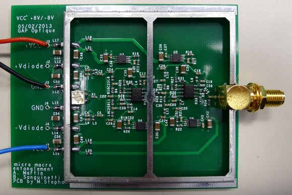
He was tasked with measuring the light intensity of two photodiodes. The expected impulses picked up by those components will be less than a nanosecond in duration, putting some special design constraints upon him. To register this signal he’s using three cascading op-amps per input. To ward off false readings from RF interference he also designed in the shielding which you see surrounding the majority of the circuit.
His package choice for the THS3202 op-amps is quite interesting. He didn’t go with the footprint that includes a thermal pad to dissipate heat because he didn’t want to interrupt the ground plane on the underside of the board. To keep the parts from melting he added an aluminum spacer that contacts the top of the package, then a heat sink that covers the entire shield frame. In a future revision he figures he’ll move to a four-layer board so that the can opt for the MSOP package that does the work for him.


That is amazing. It’s an impressive design (not that I can fully comprehend.)
Ehpic. freeze sprays will save the world!!
I think I strive to be Limpkin — I built a laminated PCB buisiness card, an APD readout circuit using the MAX0601 4GBPS comparator (very similar to this post) and am envious of his CNC machine. Engineering ROCKS!!!!!!
In addition, our university (University of Maryland in the USA) is quite active in research of quantum entanglement too!
Wow, neat!
i go to UMD (collage park) and i hear talk about that allot! dont understand a word of it tho can anyone really say they understand quantum physics? XD
Please tell me you’re not one of the drunk frat boys who goes to the various parties on College Ave on game weekend and then pisses on our yard while stumbling back home in the evening…
I have a long running question I have been trying to answer.
Go ask one of your physics guys, does Quantum entanglement work over the boundary of a black Hole, and if not why not?
Since there is no ‘weight’ in the transmission mode of QE.
i will never understand RF black magic …. but it is inspirational!
Hopefully in this case, the RF black magic cancels out the Quantum Physics black magic. Or they stack. Probably both, simultaneously, actually.
Haha, comment of the day right here^!!!
I took a glance at your write-up, and had the following question:
You’re using a current feedback amplified, which you say precludes the use of teh transimpedance topology of amplifier. How do you ensure that the bias conditions don’t shift on you based on the output current of the photodiode? Are you depending on the bias tee structure to ensure that the bias point does not shift, rather than the active drive of a transimpedance input?
I’ve been looking into some high-speed amplifiers for a project I’m doing at work right now. I don’t really need the speed (I’m looking for a 100ns pulse), but I need high temperature operation and TI has a part that works. Unfortunately, this part was also low impedance input, meant to receive signals from a 75 ohm video line and amplify and distribute the signals. There may be other amplifiers on the market that have a high enough input impedance to do a transimpedance amplifier, if you run into problems with biasing.
When I was at JPL (as an intern), I worked in a low-noise RF amplifiers group. They had to cryogenically cool their amplifiers to reduce the noise to where they could receive the incoming signals. I would suggest doing something similar if you run into issues with nose. Any small signal has the opportunity to be overwhelmed. They were using HEMT amplifiers, cooled to about 10K, depending on the amplifier. A number of radio astronomy rigs are very similar. I would suggest looking into supercooling the device to improve its noise properties if you have issues with nose. You don’t need LN or a Gifford-McMahon cooler to get superlow temperatures (in fact, the electronics may not work at those temperatures), a thermoelectric cooler should do the trick. Pull the heat down to the low-end of the rated temperature (-55C for mil-rated parts, -40C for auto and industrial, 0 for commercial) and you should reduce the thermal noise induced in the system by a significant amount.
I would highly suggest using at least 4 layers to implement this board. This way you can have a solid heatsink (usually the pads are connected to ground, by the way) on the board. I would go as far as conformally coating the board and slapping a TEC on the backside, and pulling the temp down to about -40C or so just to see what that’d do. If you want to do that, make sure you have C0G capacitors (the more expensive, larger ceramic caps) for all the critical values, X7R’s (the other major wide-temperature rated ceramic cap) vary by 15% over temp.
You could try a JFET amplifier as a impedance adapter for your OP AMP.
Mind sharing the part# for that low impedance input amp? I’ve been meaning to fix a few issues with a livewire underwater camera system and I’m dealing with quite a bit of signal loss in sending CVBS over ~1500ft of RG-179 (loads of attenuation). I can’t replace the cable unfortunately as it’s joined with 7 other conductors, built into a kevlar mesh strength member and coated in polyurethane. A good video amp at the source would probably help quite a bit instead of trying to amplify a noisy, degraded signal at the receiver end.
Texas Instruments OPA820. In a packaged form, it’s available in SOT-23-5, and will do industrial temp (-40 to 85). In die form, you can get one that’ll do oil well temperature (-55 to 210).
Hey everyone!
Thanks a lot for your comments… you’re giving me too much credit, I just had to follow some guidelines and use common sense :)
@KE7EHA :
– Vbias will not vary compared to Vcc as in my setup their GND are connected together. If they were not, I would just have to set the “common point” with low value resistors. At some point, I was actually wondering if there was not a high frequency variation between the two GND that was amplified by the whole chain
– the non inverting input should have a lower input impedance no?
– I actually thought of using a peltier element + watercooling… but it’d have been way easier to go for a 4 layers stackup + the ths3202 with the heatpad. We’re gonna measure the current noise in our experiment, and (who knows) we may go for cooling down the ths3202
– I couldn’t agree more… we actually have a very good experience with controlling the temperature of our boards with peltier elements!
I noticed the same kind of shielding on an LNB from a directtv satellite receiver.