We don’t know if this will come as a surprise to the regular Hackaday reader, but a whole bunch of Atmel microcontrollers have a very cool feature hidden away in their datasheets. Most of them – everything from the ATMega 168, 328, 32u4, to the ATtiny85 and 84 have a temperature sensor right on the chip. [Connor] did a little bit of research on this sensor and came up with a little bit of code that spits out the core temperature of these Atmel chips over the serial port.
The temperature sensor on these Atmel chips is accessed by writing a code – ‘100111’ for the Mega32u4 and ‘100010’ for the tiny84, for example – into the ADMUX register on the chip. According to the datasheet, the returned temperature is accurate to +- 10°C, but that can be easily calibrated by holding an ice cube (in a plastic bag, of course) up to the chip.
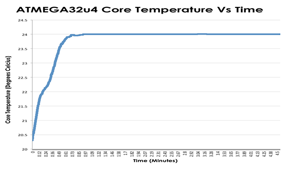
With a little more code, [Connor] is able to output the temperature of the microcontroller core over a serial port. In testing, his chip started out at 20°C and reached equilibrium at 24°C after about a minute. Pretty neat, and could be used as a temperature sensor for a project in a pinch.


I wonder what happens when you submerge an Arduino in a toilet bowl.
You know you have disrupted the industry when there is so much hatred for a product.
You get a shitty hack?
Or a piss of shit.
Been there, done that… http://learn.adafruit.com/neverwet-electronics/overview
BTW You may mock the Atmel, but for less than the cost of a coffee I can get a tiny board with one of these on it that out-performs in every way, the first computer I ever worked on. It is of the order of 1/10,000 of the price too.. do I care that the internal temperature sensor isn’t accurate to 10 decimals…. No. Do I love the fact that I can use it to control a camera sent to the edge of space on the back of a helium baloon. Heck yes… give me more of it… I may even flush one down the pan, and rescue it from the septic tank with an 808 keyring camera attached, just for the fun of it.
Dare I ask, how would you rescue it? Dig up the tank?
Better question why? I’d go wireless with that one and never ever ever plan on seeing the thing again!
In the unlikely event that I try this particular experiment… amusing though the idea is, I would make the gadget a vivid colour, and ensure that it floated. The septic tank in question is an ancient victorian construction, so moving one large stone slab gets me access to all of the unmentionable…
Being victorian and ancient (the tank that is, not me), I have had the “pleasure” of unblocking it on a couple of occasions. Tree roots and old clay pipes dont mix very well. A video of the “passage to freedom” the sewage takes might not be to everyones tastes, but I can actually see a commercial application for such a device. If you could see the problem from the inside as it were, using a cheap low cost device, it would make knowing where to dig for vitory a little bit easier.
The obvious candidate might be a “Capsule Endoscopy” module, but I suspect they are a little pricey. Food for thought… if anyone wants to try this, I have a suitable test environment they are welcome to use. Bring your own boots, I’ll provide the shovels (and the sh*t).
A few quick remarks w.r.t. atmega32u4:
* the multiplexer code has to be split: ADCSRB.5, ADMUX4:0
* there is no “4K above background”, it all comes down to oscillator speed, activity of the port drivers, package and heat sinking properties of the PCB.
* poor baseline accuracy and individual heating level suggests calibration under “typical operating conditions” is the way to go
* datasheet says: “The temperature sensor and its internal driver are enabled when ADMUX value selects the temperature sensor as ADC input. The propagation delay of this driver is approximatively 2µs. Therefore two successive conversions are required. The correct temperature measurement will be the second one.”
Always a catch.
Accuracy at +-10°C? That’s 18°F. You’d get more usable results with a random number generator.
They really are that bad. The XMegas are even worse. I gave up and put an external temperature sensor on the board.
+/-10K is ridiculous, but that is just how chips come out of production (variability of doping profile and concentrations) without anti-fusing, laser trimming or calibration ROM :(
On second thought, I can hardly imagine a need for absolute on-die temperature measurements – and we wouldn’t want to solder our chips down with a stamp-sized exposed pad of hell to fix the thermal resistance, would we.
+/- 10 is only the offset error, and that’s why you have to calibrate it before you can use it. Once it’s calibrated with an ice cube (or whatever) you can measure single degrees quite accurately (see the graph at the top of this page – does that look like ‘random numbers’?).
The datasheet says the voltage sensitivity is approximately 1 mV/°C – easily measurable using a 10-bit ADC and the 1.1V internal reference. It’s not good enough for a weather station I admit, but hey, it’s a free feature of the chip.
Brian, I’m really refraining myself from posting a shitty sarcastic comment. You’re presenting someone’s discoveries in the AVR world as a breakthrough we should all be informed about.
http://playground.arduino.cc/Main/InternalTemperatureSensor
> hidden away in their datasheets.
Isn’t this exactly where you would expect this kind of information?
There also is an application note:
http://www.atmel.com/images/doc8108.pdf
Good link, but I wonder why the thing is there in the first place? Random number generation? overclocking? What?
Overtemperature protection I’d guess. You can use it to automatically shut down critical hardware in case of overheadting.
Btw, one cool hack could be to use the temperature variation to estimate power consumption of the AVR. Since all consumed electrical energy in the AVR is converted to heat, the following relation is true:
P_AVR[W]=deltaT[K] * k [W/K]
Where k is a heat transfer coefficient which is roughly a constant for the type of MCU.
k can be determined by measuring P_AVR externally.
Probably flash programing temperature compensation… see: http://www.cypress.com/?docID=44026
That seems to be it, interesting, thanks.
What?!! There are PDFs with most if not all of the details of the functions a chip has and details of how to use said functions?!?!?!!? Someone needs to need submit this tip to hackaday right away!
I suggest wording like this;
“Here in the hackaday labs we always had to decap and reverse engineer our components to work out how to use them until [ArduinoFan29] sent us a tip that most chips have publicly available documentation! [ArduinoFan29] is also launching a kickstarter that will distribute links to google to all backers so they can find the datasheets they need.”
lol that sarcasm made my day
Golf Clap
And yet, nobody so far ever used that temp sensor AFAIK. So how about that eh mr sarcasm.
with a tolerance of +-10C, who would bother? I could guess the temperature and still be closer
Not if you calibrate the temperature sensor first. It may not be terribly accurate, but it does appear to be pretty precise. It may be faster or easier to use an external sensor instead …provided you happen to have a spare sensor on hand, and can (if necessary) spare an IO pin for it.
If either a) you don’t have a separate temperature sensor on hand and don’t want for one to ship from Digikey (or wherever), or b) for whatever reason you don’t want to add another component to your circuit, then the internal temperature sensor will be useful to know about.
http://en.wikipedia.org/wiki/Accuracy_and_precision
As I suggested earlier, it could also be used as the basis for random number generation, that’s how they often do it I think, a ‘flaky’ diode.
Of course in that case it might be a bit ‘too precise’ for some uses, but still though, it’s just one idea.
I’m not sure we are quite understanding the problem here.
I dont think the accuracy is +/- 10 C, it may be +/- 10 %, but 10% of what exactly.
Having just tried the experiment, (sadly there is no rule on this board that says you can’t comment till you have tried things yourself).. based on the code here.. (http://playground.arduino.cc/Main/InternalTemperatureSensor) I can confirm that the serial monitor says the temp is 12.0C and the clock next to it with built in temperature says it is 11 C – Time I turned the heating up in the workshop perhaps, but certainly in a straw poll of one, these results are pretty close.
Furthermore the readings on the atmel dont vary by 10 degrees, in fact they are pretty rock solid… variation between readings is less than 1 degree (nearer 0.1 in reality) .. so 10 degrees +/- 1 degree (which is 10 percent of 10 degrees) looks not too bad from where I am sitting… I could of course be completely wrong, and the Atmel team decided to include a temperature sensor that fluctuated wildly by 10 C .. but I doubt it.
I think this is more a matter of understanding the problem, and how the device actually is intended to work and calibrating the result,
texas instruments MSP430 chips also have internal temperature sensors as does the stellaris/tiva launchpad.
Both also suffer from lack of accuracy.
Yo dude, I managed to read the datasheet, dude. No kidding. Bow to my superiority.
Oh you must be the guy who hosts all those projects where they use the temp sensor, impressive site man.
Have you read the entire ‘328 datasheet? Yeah, me neither. It’s 35MB, and 660 pages. The temperature sensor is described in section 24.8 on pages 252 and 253.
I would not call what Connor did a hack. He used a feature for its intended purpose. That feature, however, does not seem to be either well known or commonly used.
Thanks for saying what I said but in a more eloquent and less snide manner. That will probably work better.
Not all of them are that long. The datasheet for the atmega48/88/168 is 377 pages and I’d estimate it’s about 50-70% charts and register descriptions.
That page is not aimed at the majority of you (posting sarcastic comments). It was aimed at beginners who may not know about this feature since it isn’t mentioned very often. I am not claiming to have made a breakthrough discovery, I’m just attempting to provide an example to those who are trying to get this feature to work.
Not entirely useless…
“The internal temperature sensor can be used as a seed for random numbers:”
http://www.arduino.cc/cgi-bin/yabb2/YaBB.pl?num=1294239019
Using entropy to generate entropy is a good way to be cool and random.
Oh Geez! Don’t give them the idea they can measure ambient temp with a sensor embedded in the chip for the purpose of monitoring processor temp. Nothing in the world more frustrating than thinking you can do something and then when you do it it’s not measuring what you thought it would. It’s a great reference for correcting the bad-gap reference readings, or perhaps to GUESS at the crystal osc deviation, or perhaps to give advance warning of imminent melt-down…. All unlikely to be needed.
“, but that can be easily calibrated by holding an ice cube (in a plastic bag, of course) up to the chip.”
Well, assuming you measure the temperature of your ice cube before hand. Remember, just because it’s ice, don’t mean it’s 32F/0C. It can be colder then that. That’s just the temperature it freezes at.
Good point (however the melt water on the surface of the cube will be as close to 0 C as to make no difference for the purposes of this debate, so just ensure the cube is starting to melt).
One final point regarding peoples understanding of the sensor.. if you actually take the trouble to read the Atmel calibration notes (http://www.atmel.com/Images/doc8108.pdf) you will see that with a little but of care, it is perfectly possible to A) Understand how it works, and B) Obtain fairly accurate results from the sensor, by ensuring you apply the correct calibration algorithm.
There is mention of +/- 10 C drift from a linear relationship between the sensor diode’s temperature curve, and the actual temperature.
This is *not* the same as a 10% inaccuracy, it is simply that the diode has an almost, but not quite linear linear relationship between voltage and temperature.
The document then explains how to compensate for this.
As ususal, if all else fails *read* the instructions.
.. so after calibration “This can result in very precise temperature measurements, sometimes as accurate as +/- 2°C. “… easily as good as the thermometer on my car’s dashboard, what do you want for your $2 per chip?
My educated guess is that the temperature “feature” was originally
intended for chip verification/characterization use. You see the pages
of chip graphs at the end of the datasheet where they plot power
consumption vs Vcc *over temperature* etc. Someone would also need to
measure the temperature of the silicon die if they are doing
verification of the chip design at the corner cases.
They don’t calibrate it at factory as it is not something the *chip
guys* thought the customer would use, but probably someone at marketing
put it on the “feature” list anyways.
Very likely this might be one of the greyed out mux value on their older
chips. e.g. ATMega8. So it would more HaD news worthy for finding out
the undocumented.
Chip testing (time) cost money and they aren’t going to spend minutes on
a *production* tester just to get the chips temperature calibration
done. Same as those “Characterised by design” parameters on datasheet in
general.
By the way, it is listed on the page 1 of the datasheet in the bullet
points, so no excuses for the datasheet is too long to read.
– 8-channel 10-bit ADC in TQFP and QFN/MLF package Temperature
Measurement
– 6-channel 10-bit ADC in PDIP Package Temperature Measurement
Wow, talk about a tough crowd! I thought the point of hackaday was to inspire people to learn more, not shame them into never posting again.
While I certainly wouldn’t use the builtin temperature sensor in a sous vide cooker, since I’d at least have to subtract the die temperature change caused by CPU activity. But I did put it to good use in my Charlieplexed hearts! https://wiki.hackmanhattan.com/Charlieplexed_PWM_Heart
Just used my ATtiny to measure how cool all the haters are here: not very cool (+/- 2K)