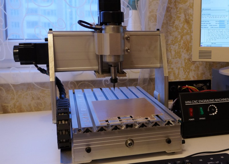
If you frequent any CNC Forums out on the ‘web you’ll find that these Chinese 3020 CNC routers are generally well received. It is also common opinion that the control electronics leave something to be desired. [Peter]’s feelings were no different. He set out to make some improvements to his machine’s electronics such as fixing a failed power supply and adding PWM spindle control and limit switches.
[Peter] determined that the transformer used in the power supply was putting out more voltage from the secondary coil than the rest of the components could handle. Instead of replacing the transformer with another transformer, two switch mode power supplies were purchased. One powers the spindle and the other is for the stepper motors. So he wasn’t guessing at the required amperage output of the power supplies, [Peter] measured the in-operation current draw for both the steppers and spindle motor.
As received, the spindle speed is manually controlled by a potentiometer on the control panel. CNC Machine Control software, such as LinuxCNC or Mach3, has the ability to control the spindle speed by using PWM. It turns out that the 3020’s control board and spindle motor driver are designed to do this, it is just not hooked up. After some poking around on the board, all that was needed to finish the job was to add two jumper wires and flip one DIP switch.
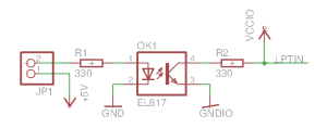
The control board also has inputs for limit switches that are unused as shipped from the factory. Through some investigation it was found that the limit switch inputs are opto-isolated. Now the machine can be run without worry about unintentionally running out of travel. This and more is documented on [Peter]’s site, including all of the parallel port pin functions and machine specifications.


Now just get rid of that “spindle”. Sticking a er chuck on a dc motor does not make a routing spindle, the chinese should be ashamed of themselves for marketing it as such.
Really? Do you have a flintstone router? Because last I checked, they are all have electric motors directly attached to a chuck (unless you are implying that a DC motor is somehow inferior.)
Do you know for a fact that that motor was not designed for lateral loads?
I work on CNC machines for a living, just spent two days pulling a spindle out of a Matsuura HMC to send in for rebuild. There are lots of different kinds of spindle. Not all are electric motors tied directly to a chuck.
And yes, I have seen close up photos of this and there is no chance that this has angular contact bearings, tapered roller bearings, or even a radial/thrust bearing assembly.
Besides the bearing issue there is the shaft itself. If there er chuck was integral to the armature that would be one thing. But the amount of stick-out with a relatively tiny motor shaft makes a horrible spindle design.
Nothing wrong with a dc motor, it would be find to belt drive or directly drive a spindle.
To be fair, these are actually listed and sold as engravers.
There are a lot of vendors selling the spindles for more than just engraving.
http://www.ebay.com/itm/CNC-400W-Spindle-Motor-ER11-Power-Supply-Speed-Controller-Mount-bracket-/271377163462
Still light work being represented. That looks like wax to me.
Basically, this works fine for what it was intended for: essentially a CNC dremel. I wouldn’t be silly enough to buy something like this to do anything more than milling/drilling PCBs, thin panels, maybe some acrylic or even carving soft woods.
I don’t think (hope) that most people would expect more than that out of something like this. Not everyone needs or can afford a professional level CNC router.
For a bit more you can get one of these chinese spindles which are actually pretty decent spindles:
http://www.ebay.com/itm/CNC-FOUR-BEARING-ER11-1-5KW-AIR-COOLE-SPINDLE-MOTOR-AND-MATCHING-INVERTER-/251032652684?pt=LH_DefaultDomain_0&hash=item3a72b64b8c
The 1.5 Kw water cooled spindles are just to big and heavy for this little machine.
That is even if I could get it mounted.
Perhaps a 800 watt size would be better.
There is a definite need for a good upgrade spindle for the 3020 machine.
Would you happen to know a replacement spindle I could stick in the machine instead of that one? The mounting ‘claw’ is 52mm in diameter and 52mm high. (Is there a standard on spindle motor dimensions?)
My first choice would be a Precise or Fischer-Precise spindle. They are very good quality, ABEC-7 or 9 bearings. I have one and it is very, very nice. They pop up on ebay now and then. A friend picked up one of the little SC52s with the drive for a few hundred.
Second choice is one of the small chinese spindles, here is an 800w one that would work for your size of machine.
http://www.ebay.com/itm/NEW-800W-CNC-Router-Water-Cooled-Cooling-Spindle-Motor-1-5KW-Inverter-Drive-/121121501567?pt=LH_DefaultDomain_0&hash=item1c3367717f
Now it is water cooled so you will have to rig up something for that. You can get a fan/pump/radiator designed for water cooling PCs and use that. Second issue is you will need a VFD to drive it. You could get the chinese one that is optional with it but then you will have to run the spindle off 240v which may not be very convenient. I would get one of these to run it:
http://driveswarehouse.com/p-2602-wj200-007mf.aspx
This will allow you to run the spindle off 120v. It is also a lot better drive. With a VFD you can control it through a 0-10v analog signal and there are lots of plans out there to build an interface for linuxcnc or pre made boards.
Thank you for the suggestion. Water cooling is not a problem and I live in a 220V country (Russia).
However, I really don’t know how I would replace the spindle. The one you suggest has a 65mm diameter. The motor fixture definitely couldn’t accomodate anything differing from 52mm by even a few mm. I mean, look at it: http://i.imgur.com/hP7HbNz.jpg
Do you have any ideas for this? It seems pretty monolithic.
While we’re at the topic of CNC tools, I’ve long had this idea for a CNC with a replaceable head: spindle / PLA extruder / pick&place head / laser plotter / …. Do you think this makes sense?
Two options,
1 Find someone with a lathe and a boring bar and bore out the existing mount to the new spindle’s size. There ought to be enough “meat” in the mount to go up to the next size.
2 Buy a new mount for that spindle: http://www.ebay.com/itm/65mm-diameter-mount-bracket-Clamp-for-spindle-motor-A1-/250851118965?pt=LH_DefaultDomain_0&hash=item3a67e44f75
I think there was a kickstarter for someone who was making a extruder head to mount on any generic mill. This should work fine as most mills should move fast enough to do the job. You could probably do the same with a pick and place set up but you would probably want a faster machine. You dont need the resolution you need when routing/milling so you dont need to be geared down as much.
As for the laser. No. If you want a laser cutter build a dedicated machine. Some people use laser diodes which are just terrible choices for laser cutters. The beam is just awful and is the wrong wavelength to do anything real useful. Also, you want a fast and light gantry, especially if you want to get one of the chinese laser controls and do raster engraving. There are no cutting forces involved so you can get away with a lot. Look at the buildlog.org site for open source designs.
Oops, I didn’t see the picture of the mount. I would pull the mount off and cut the old one off and mill it flat for the new mount. There has got to be someone out there that can help you with that.
1) actually won’t work. My spindle has d=52mm, yours has d=65mm → 13mm of difference. At thinnest point that spindle mount is 4mm thick… and I’d need to bore out 6.5mm
2) is what I thought about, but I’m really not sure how to attach that mount to the machine. I can see three options…
1. Saw off existing mount, weld new one there. I think welding aluminum is really nontrivial? And you’d need to do it really straight. I’d need to find a professional to do the job.
2. Saw off existing mount, drill holes there, screw the new one somehow. Additional problem is that existing is 8cm wide, and the “platform” of the new one is 12cm wide / body is 9cm wide. No idea how to securely attach them this way. However this is attractive because I can make changeable heads this way.
3. Throw existing mount out completely, make a new one from scratch with a new ballscrew nut and those cylindrical guides. That’s a bit over my head too…
If the new mount is bigger than the one you already have… any chance you can mount the larger one on with screws to the OTHER side of that vertical plate? Keep the old mount in place if you need the lighter duty motor?
I picked up one of these 3020s a couple weeks ago. It has a 400w spindle, and I’ve wondered what it might take to get an 800w spindle on to it. This thread sparked an idea.
Look at this z-axis: https://www.ebay.com/itm/403622284912
I could remove my entire z-axis assembly. Then remove the sq. aluminum extrusions from the new z-axis.
The distance between the orange plates on the new z-axis is 135mm, which is about 20 mm more than the x-axis slide carriage.
A 10mm plate, top and bottom, could serve as an adapter to screw to the x-axis and the end-plates of the new z-axis.
I hope that made some sense.
Reasons for removing the extrusions would be to keep the new z closer to the x so to not lose working area, and to keep it close for stability.
FWIW
By the way, I didn’t want to make laser *cutter* like this, rather a laser *plotter* — to expose photoresist with an UV led that way. It was just a random idea though, I don’t have a specific use case for it…
Even with that you still need to completely enclose the machine in opaque material to be safe. Even specular reflection from one of these diode can cause eye damage. You still run into the crappy beam quality problem. Scattered light around the beam exposes the resist as well and the roughly gaussian beam profile gives soft edges. The beam really needs to be passed through a spatial filter before delivery.
I was thinking of feeding the UV beam into a thin optic fiber, then moving that around, possibly moving the entire assembly around, but not directing the LED straight on board.
I don’t think I could get a 50 µm thick fiber though, and that’s the resolution I get right now with laser printer photonegatives, so… probably not worth it.
Launching the beam through a fiber brings all sorts of new problems, least of all a 50um fiber does not give you a 50um beam. You need optics after the fiber to collimate and focus the beam.
1) tiny cutting tools require very tiny runout. Looking at that klugey spindle, I’m guessing runout is measured in the thousandths. My Taig runs .0002 if I clean the spindle before chucking up. Therefor, it runs tiny end mills well.
2) too fast for all but the smallest end mills.
Two properties that are at odds with each other.
I have an 800w Chinese spindle Attached to a 3040T with custom built controller. I run .5mm 2 flute tapered end mills in brass and aluminum 8 hours a day 5 days a week. Engraving to 9/1000″ and cutting 58/1000″. I have been running the same spindle at this capacity for over a year now. It all depends on the manufacturer and the bearing quality/ setup. (And I use cheap end mills at $4 each. I use 1 end mill for about 14 hours of cutting/ engraving before tossing. I’d say this isn’t bad for a complete CNC setup of around $3000 and around $4/ day running cost, including electricity to run it.)
The ‘LinuxCNC’ hyperlink in the article is b0rked. I have no idea how to find their website without a working link either!
http://lmgtfy.com/?q=http%3A%2F%2Fwww.linuxcnc.org%2F
I see jocular comments are lost on some :P What kind of low-forehead do you take me for!?!?
Of the two jocular comments I give higher marks to hojo.
thanks for recognizing.
I know of no rule requiring me to honor your sarcasm.
http://lmgtfy.com/?q=linuxcnc&l=1 is better. Yours assumes you already know the url for the url you are looking for.
hojo,
http://www.linuxcnc.org/
The link is now fixed in the post. Thanks!
Got the same CNC, I was wondering how I could get it better (some missing steps on X axis everyone ?). I was thinking about adding end switches to mine to get autocalibration with emc2
And I want to add, thank you for your work. I was guessing there was some unused components inside this beast and then you confirm it by using it. Excellent !
I don’t get any missing steps on either of the axes. Can you compare your parameters with the one I have listed for EMC2 at the end of article? Also, does EMC2 complain about jitter being too high?
I’ve just seen (yesterday) that i get missing steps only with the X axis, when I make a sweeping movement with high speed. I think i could correct this with your settings (because i’ve made mine real quick and dirty) and by tightening my X axis (i think it’s a little bit untightened). So don’t worry about this, I think it’s a minor problem. EMC2 doesn’t complain about jitter being too high. Thanks for reacting so fast in order to help me, that’s a community-thinking-way !
I ran EMC (LinuxCNC) for a while on a larger style machine. Only thing I can suggest is slow down your speed. I don’t know the specifics of your steppers and board, but I’m running NEMA23 and was cutting at like 50 IPM.
I’m using the same than this article. I think it’s NEMA23 too. The model is a 4020t-dj.
I was considering buying one of these to mill the square holes in some of the housings we use and after reading these posts I probably will buy one or the 3040 model.
Nothing I read here has scared me away, even the “it’s not a real router” comments. The tolerances I need are in the +/- 0.05 range”, not the +/- 0.001″ range and the machine can take its time making the holes.
There is a misconception that if you machine is sub-standard you can just “take your time” and everything will be fine. This can apply to some machine like a low powered laser cutter where you can slow down the travel speed for thicker materials.
This does not apply to machines that cut materials. When cutting materials you need to have tooth engagement in the material being cut. This applies to mills, lathes, and even things like table and band saws. If you do not have tooth engagement you are just rubbing the material. This causes several things to happen, mainly tool wear and heat, some materials work harden. Heat is a huge issue, especially if you are cutting wood and plastic. Wood burns and plastic melts. When plastic melts it encapsulates the tool and snaps off bits or locks the took into the work.
Buy an appropriate machine for what you want to do in the first place and you will be much happier in the end. Even if you have to save up a little longer to get it.
Low power laser cutters can be coerced to cut thick stock using slow speeds and/or multiple passes but the resulting cut is often of inferior in comparison to a higher powered laser cutter. Kerf angle and thickness, edge sharpness, fine cut details, edge finish and optical clarity ( often important for acrylic work but less so for plywood ;) usually degrade when one is forced to cut using slower speeds or multiple passes.
A high power laser lets you move the beam quickly through the material to minimise the thermal energy deposited in material surrounding the cut. Also, hot gases generated during the cutting process only have one opportunity to mar the edge and surrounding material.
Sure, you don’t break bits but there exists a similar distinction between cheap laser “engravers” and commercial/high power laser cutters.
I was just making a comparison between machines that you can go slow on and ones you cant.
I also work on lasers from my little 7 watt Q-switched UV yag to the big 4400w Bystronic at work.
got 2030t from ebay.
best buy ever. 3 years so far = 0 problems.
like a clockwork.
will mill anyitnhg from mdf to 3/4″ acrylic.
lots of power. linux cnc ftw!
Next time, go to AliExpress, it’s cheaper. And you can buy a lot of bits and chucks for nothing ! These machines are awesome for PCB engraving.
I would like to buy one of these, if it can work with aluminium the better. Which one should I buy and from where?
This one seems to be identical to mine: http://www.ebay.com/itm/321262587603
I really can’t say whether it works with aluminum, didn’t try that yet.
I’ll know sometime after Saturday – my machine is supposed to arrive Saturday.
out of curiosity, does anyone own a 3040 machine? On the pictures they seem to have “real” ball screws. Any practical problems to be aware of?
I have a 3040 that I use to engrave and cut brass and aluminum. I use a custom built controller and get 350 ipm Rapids and can easily work at 100 ipm. It uses chrome plated ball screws. I have used mine problem free 8 hours a day for over a year. I purchased from AliExpress.com. Just make sure you ask a lot of questions about the machine. Spindle size and bearings, stepper motor torque ect…
I got a cnc machine that is exactly the same as yours on the picture. But I cannot get it work with mach3. The steppers on my CNC are not moving when I hit the tab key in mach3 and try to move it with the arrow and page-up/down keys. I have a motherboard with DB25 parallel port on it and run windows 7-32 bit on it. I was wondering if you could help me with this issue by telling me how you actually configured this machine.
I appreciate your help!
I’ve described the LinuxCNC configuration in http://lab.whitequark.org/notes/2014-02-12/cnc3020t-emc2-configuration-and-hidden-features/. I have never worked with Mach3, though. You may try searching http://cnczone.com/, I think they had a few threads on this topic.
Hi all I d like to buy a cnc 3020 for building hair wood combs. strong wood 10mm. And I find a nother one is call stepcract but they told me is not k for .industrial production. Now in wandering if 3020 will do the job. Any review fro somebody ho has one thanks
You will need at least a 800 watt spindle for use on harder wood. You can find some good 3040 machines with an 800w spindle at aliexpress.com
To Adrian
I have had my 3020 cnc mill for a solid year now. I have put 2000 hours of machine time on it with out
any problems with the machine as shipped to me. Most of the work I do is out of various types wood and hard polymers. So you shouldn’t have any problems doing what you want. What you have to look out for are feed rates, spindle speed, depth of cut and your tool step over. Here is a good set of parameters for you to use for soft woods like pine poplar. (Depth of cut .03125″, feed rate 24″ per minute, step over 75 percent of tool diameter, and spindle speed at 5000 rpm ). Do not try to machine any type of metal with the 3020 mill. It is not designed for it.
hello adrian
just wondering is the machine still going as i have bought one with the black control box and i am wondering is the control box good for long time use also do your stepper motors get very hot when in use for a long while
and is there any advice you can give on the machine
thank you very much
Nice Job! Can you help me with my 3020 cnc for PWM spindle control?
I put to second position the jumper, put 2 wires, I tried on mach3
Can you help me with settings for mach3 and some tips?
Thank you!