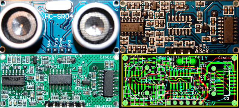
[Emil] got his hands on a dozen HC-SR04 ultrasonic sensors, but wasn’t too happy with their performance. Rather than give up, he reverse engineered the sensor and built an improved version. Hackers, Makers, and robotics enthusiasts have had easy access to standard sonar platforms since the early 1980’s, when Polaroid began selling their 6500 sonar modules. A number of companies have released sonar boards since then, notably The Parallax Ping))) module. The HC-SR04 appeared on the market a few years back as a low-cost alternative of the Ping.
[Emil] found that the HC-SR04 would work reliably on hard surfaces as far as 4 meters away from the sensor. However, he got a lot of bad data back when using soft sided targets, or when no target was present at all. [Emil] reverse engineered the schematic of the HC-SR04 and found some interesting design decisions. A Max232 RS-232 converter chip is used for its +-12V +-10V charge pumps. The charge pumps are connected to create 24V 20V at the ultrasonic transmitter. A mask programmed microcontroller manages the entire unit, commanding the ultrasonic transmitter to send 40Khz pulses, and listening for returns on the receive side of the system. [Emil] believes the micro is running in polled mode, due to the fact that it sometimes misses pulses. Even worse, the micro runs on an unmarked 27MHz crystal which had quite a bit of drift.
[Emil] solved these problems by creating his own PCB with an ATtiny24 and a 12MHz crystal. He increased the pin count from 4 to 6, allowing the ATtiny to be programmed in circuit, as well as opening the door to I2C and SPI operation. To build the boards up, [Emil] first solders his micro and crystal. He then uses a hot air gun to move all the components from the HC-SR04 board to his own. The new boards are still being tested, but [Emil] has posted his PCB and BOM data. He’s also promised to post his AVR code when it is available.


>The charge pumps are connected to create 24V
The original author got it wrong. The MAX232 chip runs off 5V (minus a VCE drop), which then get boosted to 10V and inverted to -10V at no load. So at best you would get 20V, but in real life with actual load there would be less.
You could make 1.5V AC current from an AA battery, connect it to a rewound MOT and get hundreds of amps at very low (safe) voltage.
To get to hundreds of amps, your output voltage is at a few millivolt as there is only so much current you can draw from an AA cell in the first place without its voltage sagging.
I(P) * V(P) = I(S) * V(S) from: http://en.wikipedia.org/wiki/Transformer
So assuming that you can get 1.5V @ 1A without any sagging and I*R switching losses,
to get I(S)=150A at the secondary, V(S)= 10mV
Since V = I*R, to really get that 150A, let’s short circuit the secondary side.
R = 10mV/150A = 67μΩ which is highly unlikely.
What are you smoking?
Did you perhaps mean hundreds of volts at a low current?
@RP I think you’re right, that would make a lot more sense. Single-transducer designs often work at much higher voltage levels.
Could be he’s seeing some overshoot, no load it’s averaging out to look like 24V, or assuming they’re running on the old +/-12V. Depending on the ping rate, using that overshoot to charge up a cap, it might hold up long enough to get the ping out.
(hope that makes sense….)
Seems to me, the older 7660 charge pump chips had a bit of overshoot on them. Not a lot. It’s been a while, but I seem to remember, using those chips that I always seemed to have a little bit more than what I expected, and it was from overshoot, as long as there wasn’t a big load on it.
Have not looked at the charge pump in this chip, so….
Not likely. It is a charge pump. Basically you charge up a cap (flying cap) in parallel with the 5V rail, then you connect the cap in series and dump that to a cap to get 10V.
It is on a PCB, so unlikely to get too much trace inductance tohave glitches. Ockham’s razor: It is more likely the person *assume* EIA232 is always +/-12V instead of reading the datasheet.
So let’s say you managed to get 12V at the output, the current would flow from the output back to the source as that current would flow from the output to the cap as it is higher than the caps. When that cap is connected in parallel to the 5V, since the cap carries a higher voltage, there would be a current flowing from the cap back to the 5V source. I have actually used that as a divide by 2 power supply to leech power from a serial port.
7660 charge pump is a a bit different as you need external 2 external diodes to get the 2x output (so 2 diode drops). Not likely to get any glitches as the output filter cap they recommend is 10uF unless you have messy wiring on a breadboard.
I have a HC-SR04 ultrasonic sensor which I need a circuit to make it send a pulse to sense an object in a continues pulse and receive some type of volts back. Can you suggest a possible board to do this or circuit.
Great catch tekkieneet. I’ve updated the post to reflect the correct voltages. Now I’m wondering what are the chances it’s a real MAX232 chip, or some sort of clone.
I don’t know how the ultrasonic transducers work, but if they’re piezoelectric, there’s essentially zero current going through them, so it sounds plausible to me that the MAX232 can drive it… a very short pulse at the higher voltage is all that’s needed to swing the element from one extreme to the other, then current stops flowing. A small cap in charge pump could deliver that, no?
That is what it does under DC. When you are driving the transducer with at ultrasonic frequency (i.e. AC), there is current flow charging and discharging its capacitance.
e.g. http://inmotion.pt/documentation/maxbotix/MB1100/MaxSonar-UT-Datasheet.pdf
“MaxSonar®-UT High Performance Ultrasonic Transducer”
>Capacitance: 2400 pF (+/- 20%)
>Operating Frequency: 38KHz to 42KHz
I’ll let you work out the current yourself.
Excellent hack! Isn’t it possible to get transceivers separately, though, to avoid the need to unsolder existing modules?
Yep you can buy the piezo elements separately from any circuit. Usually as a pair of transmitter / receiver, so they’re guaranteed to be on pretty much the same frequency. Dunno why this guy didn’t, I suppose it saved him having to build the rest of the circuit himself.
Yes, but I don’t think you’d find them cheaper at low volumes.
So will this have increased range and/or better sensitivity to soft things?
A little understood point: two antiphase +/- 10 V signals driving a single load will look like a 40 V signal at the load: quite a neat trick to use the MAX232s this way!
Hi, I can use some help from guys that worked with these type or other types of transducers. I need a device that can emit ultrasound at different adjustable frequencies. This is set at 1 frequency, probably due to crystal am I right?
I also dont want a burst but a continuous soundwave, hooked up to a PC or battery operated. I would like to see what frequency its emitting (control) at and also recieving ultrasound, for the bats in my garden to see what exact frequency they use.
Anyone interested to help me or guide me to the right stuff that does what I want? Much appreciated.
djstandove AT gmail DOT com
This is a fixed frequency device because of the transducers – both the transmitter and receiver are tuned to the frequency to get maximum range.
Bats do not use a fixed frequency – they use a chirp with varying frequency. The common device for listening to that usually “down shift” the frequency to audio range by either slowing down the replay or using a beat frequency.
Believe it or not, Wiki is a good start.
FYI: I have continued some of the work from Emily – a more current version of the schematic and AVR test code to drive the transmitter. They are part of my project page.
https://hackaday.io/project/5903-sonar-for-the-visually-impaired/log/20061-ultrasonic-module-lets-get-physical
Did anyone work out the AVR code for the transmit/recieve pulse timing? I have not been able to locate any examples.
Has anyone been able to find the firmware for the ultrasonic (pic or whatever mcu is used)?
Interesting idea. I don’t know that anyone’s tried. If I’m wrong, let us know and we’ll run a blog post!