3D Printers have come down significantly in price over the past few years. Nowadays it is even possible to get a 3D printer kit for between $200-300. It’s arguable how well these inexpensive printers perform. [Jon] wanted a printer capable of quality prints without breaking the bank. After researching the different RepRap types that are available he concluded he really wasn’t up for a full machine build. He had previously built a CNC Router and decided it was best to add a hot end and extruder to the already built 3 axis frame.
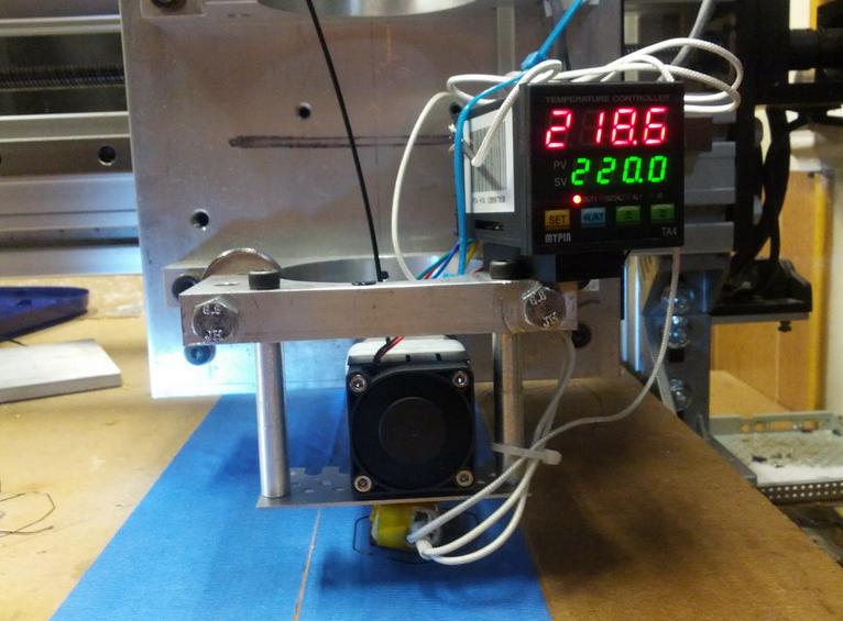
The CNC Router frame is made from aluminum, is very rigid and has a 2′ by 2′ cutting area. All axes glide smoothly on THK linear bearings and are powered by NEMA 23 motors driven by Gecko 540 stepper drivers. The router was removed from the machine but the mounting bracket was left on. The bracket was then modified to hold the extruder and hot end. With 3D Printers there is typically a control board specifically designed for the task with dedicated outputs to control the temperature of the hot end. Since [Jon] already had the electronics set up for the router, he didn’t need a specialized 3D Printer control board. What he does need is a way to control the temperature of the hot end and he did that by using a stand-alone PID. The PID is set manually and provides no feedback to the computer or control board.
 [Jon] used liked Mach3 for controlling his CNC Router so he stuck with it for printing. He’s tried a few slicers but it seems Slic3r works the best for his setup. Once the g-code is generated it is run though Mach3 to control the machine. [Jon] admits that he has a way to go with tweaking the settings and that the print speed is slower than most print-only machines due to the mass of the frame’s gantry and carriage. Even so, his huge whistle print looks pretty darn good. Check it out in the video after the break…


I’d like to see more motion platforms used as multipurpose machines with interchangeable tooling. So it’s a bit anticlimactic that [Jon] made a separate 3D printer after all, just a few months later. At least the converted router was used to make parts for the new printer.
More multiplatform would be nice since they are fundamentally similar machines. The problem is that they are just different enough that it makes sense to separate them. That said there is a Kickstarter for an ambitious 5axis system with interchangeable heads but the buy-in is somewhere around the 5k mark which is a bit much for me personally. Plus if I recall correctly they have only shown it milling really light weight material like wood and foam. Where my interests are more in something that I know can do some light duty work with aluminum and maybe plunk out some PCBs.
Hi, I’m surprised this ends up on HaD over a year after the fact :D *HaD SUPRISE* I made a smaller 3D printer for several reasons.
1. I wanted to…
2. The CNC machine is large and not very portable. It sits in a room which gets almost no heat in the winter which is terrible for printing, and me! I wanted something small I could put next to my computer in the living room.
3. The CNC machine cross arm has a lot of mass (is heavy) about 35-40 pounds without the spindle in there. I do a lot of aluminum materials, so it’s built a bit stronger. Whipping a 40 pound gantry around at reasonable 3D printing speeds is hard on the linear bearings.
4. I have some nice high quality linear rails on the CNC machine. To achieve the print speeds I want, the linear rails take quite a bit of abuse. The smaller dedicated machine can move (and decelerate) very quickly because it’s gantry is extremely light and supporting only an extruder.
I was always unimpressed with FDM 3D printing quality, even on well tuned machines. I watched it for quite a few years and first saw it in person at MakerFaire 2012 and that actually convinced me it would be handy to have just for prototyping or small functional, but ugly parts, and it has been.
I hear you, on the quality issue. FFF 3D printers can do quality work, it seems you wouldn’t know it by a lot of the examples given. And doing things to really increase the quality by a large margin involves taking longer to build the part. Cutting the layer height in half doubles the build time, for example. There are ways to mitigate that, at least two slicers allow you to use thinner layers for surfaces, and thicker layers for infill and support.
The other reasons you gave are why I get annoyed at the clamor for multi-purpose machine. Almost inevitably, something needs to be compromised to do so, even if it’s just the question of cutting dust getting into your plastic.
I figured [Jon] must have had a good reason for changing his mind. That’s quite a few. Limited print speed is something I knew about, and would be an acceptable compromise for me. Wear on the machine and cutting dust contamination is something I hadn’t considered.
Hi, the concept is commonly known as a reprap millstrap, plenty of folks build that back in the days to produce the plastic parts of a reprap before they were readily available. I did a similar build with decent linuxcnc integration if anybody prefers that to mach3: http://cncprinter.com/
Sorry to jack your post but why the hell do these weird “science related” images show up in the rss feed now instead of the main image for the post? They look like crap and in no way relate to the post, can we get the old format back please?
Bloody sacrilege!
This may well have already been mentioned (to early in the morn, for my brain to recall)
But the giant whistle photo the reflected light shows an ongoing texturing or ripple pattern in the product.
I’m assuming it’s related to stepping size/resolution of the software (including user choices) and thermal recovery at the extruder tip and keeping the filament flowing
while maintaining an acceptable/minimum bond strength between layers.
yeah, I got it as to the software/programing would need some retuning, this IS the HackaDay crowd, right?
‘nother breath….
Now then. think Stress raisers. why aren’t the layers shifted about 40~60 percent at least every second layer?
Think like the weave of a wicker basket.
I just have this little brain glitch that sees that in a broad flat section of a part and have that reaction.
yeah yeah yeah, part thickness and intended usage and so forth….
Well then how about how the surface texture causing unwanted turbulence?
Seems you’d want tight control that in a product that relies on a desired specific resonance.
Not picking and saying that it’s a concern in this case,
Just asking has anyone else looked at this and pondered it.
Heck, even if only for purposes of surface smoothing and
human perception of different type textures either visual or tactile.
I also notice a slewing or whatever it’s called in the mid range of the black section.
Now assuming anyone thinks that I’m correct about the stressors
or the smoothing issues for a moment.
How did that shift get there and can that be exploited to give a
deliberate shift in the layering track?
I wouldn’t make to many hasty conclusions on a CNC to 3DP conversion thrown together just to print functional parts to make a dedicated 3D printer. There’s lots of other quality prints out there to look at from people who will tune the heck out of a 3D printer in order to print artsy stuff.
“Now then. think Stress raisers. why aren’t the layers shifted about 40~60 percent at least every second layer?”
I’ve thought of something similar several months ago. I wanted to experiment to see if it improves part strength, but I have other project ambitions too. Taking advantage of the idea means a lot of work altering a slicer or making a new one, and I’ve decided I didn’t want to do that amount of work. The best I could do, if I manage it, is write up a proof of concept program to generate g-code for a simple shape, and publish a paper on the topic. If it works, hopefully that would convince the maintainers of slicers that it’s a worthwhile strategy. But even if it proves to be effective, I can see that being hard to get implemented, because doing my strategy without messing up the surface on normal objects is complicated.
Thanks rof the feedback.
I had figured it’d be really big pain to shift the layers if the software doesn’t yet have that function.
QUICK! somebody patent before the sidewall company does.
:^D
I finally got a chance to check out the local Hackerspace today.
Nothing like your first time at eye witnessing a table top laser cutter engrave and then cut through a piece of 1/4″ plywood.
If they’ll let me back in, I might learn few of the subtitles of the lasers and the 3d printers.
My background covers a smattering of many things that pop up here,
manual machining and layout being amongst of them.
I tend to envy you guys that have come along during the major expansion of CNC.
And a post script thought: Considering we live in an age where a company could get a patent for finally getting to the logical point of putting the enclosure around the printer table/bed.
We’ve been cooking baking in ovens for how long?
Because it’s pretty self evident that the enclosure vs over and open fire works better for keeping the cake batter at an even temperature.
Maybe it’s just just me, but I figured most people would pretty well know to put the sides on when the interior work was finished.
Thus there really wasn’t any-flippin-thing to patent about doing that.
Agreed. Now just pony up the $1M USD to prove it in patent court.
Nice. The QU-BD MKE isn’t a very well made extruder or hot end though, it is very jam-prone for one. I think you’ll find other hotend and extruder combinations to be much better. I feel I wasted a couple months trying to improve the design when I could have ditched it and used something else.
Worst… Extuder… Ever… Well, maybe not, but it’s the worst one I used. I fought with that thing quite a bit to get my 3D printer parts printed and had a lot of failures. It does have a sweet spot with the hotend temperature, but it’s very hard to find it and keep it. I was planning on using the QU-BD hotends on the final printer, but I switch to a Budaschnozzle which worked okay, and now I’m using an E3D V5 which is really nice. If I did this CNC conversion again in the future to print something big I’d certainly use a Budaschnozzle or an E3D hotend for high temp materials with whatever extruder framework seemed nice. I made another post about all the stuff I tried to get the QU-BD working reliably http://www.jonshobbies.com/troubleshooting-my-qu-bd-extruder-head-jams.html
I used the QU-BD hot end / extruder with my Shapeoko 2 and Ord Bot Hadron, it was one the best hot end / extruder I have used, but only after a “lot” of modifications, I replaced the drive gear, used a PTFE lined Barrel, and used something like this extruder block and lever from
http://www.thingiverse.com/thing:153592
or
http://www.thingiverse.com/thing:43411
Yes, it takes a lot to make the QU-BD MBE work well. Replace the pulley, the plunger, the guide block. And for me, the mount plate annoyed me because I had to modify it to make it usable in the first place. I used a Makergear Simplified extruder on one machine, and a Maxstruder on another, both with J-Heads, and both worked far better than the QU-BD right out of the gate, without fuss.
Their MBE is a poor imitation of Makerbot’s extruder, and even Makerbot had changed their extruder to get rid of the daft plunger.
I had converted my Shapeoko 2 to a 3D printer earlier this year, have a look over here:
http://www.shapeoko.com/forum/viewtopic.php?f=5&t=2501&start=40
It worked very well, and I believe I remember looking over the page at jonshobbies.com for some inspiration on my own setup, the Shapeoko 2 worked very well as a 3D printer, but I wanted my CNC router back, so I went with a Ord Bot Hadron for 3D printing.
Just checked it out and read through a bit, nice conversion!
My printer is a product of this printer. TY Jon!
YW. Happy to help :)