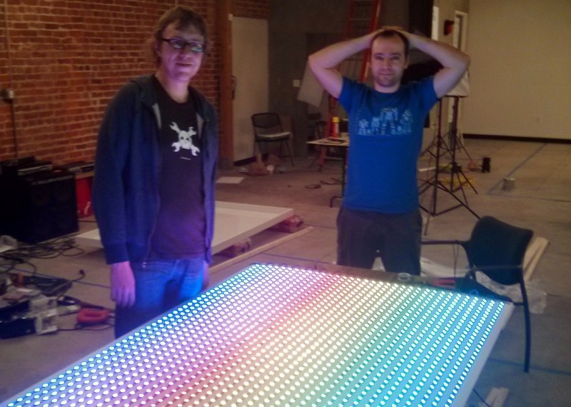
Some people would look at a massive 6’x4′ LED matrix hanging on the wall playing animations and be happy with the outcome. But [Ben] just isn’t one of those people. The original FLED (Fantastic LED thingy) was eight rows of twelve addressable LEDs for a total of 96 pixels. This spring he upped his game and retrofitted the display with 1768 LEDs.
It wasn’t simply an issue of restlessness, the original build suffered from LEDs dying. We actually featured it for that reason as a Fail of the Week. This is not strictly a hobby project, it’s hanging on the wall in the Supplyframe offices, so pulling it down frequently to fix broken parts is not ideal.
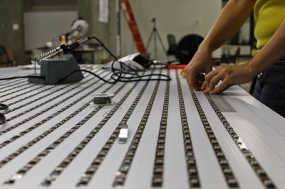
 To make FLED more reliable [Ben] sourced strips of the new APA102 LEDs which we looked at back in December. They use an SPI bus instead of the bizarre timing scheme of the WS2812. At first glance you’d think this would mean easier assembly compared to soldering both sides of each of the original 96-pixels. These do come in strips, but laying out 52×34 still means soldering to the ends of each row.
A lot of love went into making sure those rows were laid out perfectly. A sheet of white foamed PVC serves as the substrate. There is grounding braid on either end of the rows, one is the voltage bus, the other is ground. It fits the original enclosure which is acrylic and does a great job of diffusing the light. I’ve seen it in person and it looks pretty much perfect!
It’s not just the physical layout of this many pixels that is a challenge. Pushing the data to all of them is much harder than it was with 96. [Ben] transitioned away from RaspberryPi. He considered using a Teensy 3.1 and ESP8266 but the WiFi of these cheap modules is far too slow to push frame information from a remote box. In the end it’s a BeagleBone Black that drives the reborn display. This is a great choice since there’s plenty of power under the hood and a traditional (and much faster) WiFi dongle can be used.
Don’t miss the animation demos found after the break.


The “plasma animation look awesome, the fractal zoomer, however, needs more resolution…
Are you suggesting we add more LEDs? ;-)
Always.
Keep soldering ill you get HD!
Pretty awesome, considered doing a project like this, one of the big problems I saw was getting it powered.
How do you power it?
If it gets any bigger, they will need so much current, they will end up using an arc welder.
from the components list near the top of the project: “600W 5v PSU (Jameco)”
thanks
Wow, 120 Amps to power an LED display… A bit shocking when you think about it.
So not battery powered? Seems like you’d be replacing a hundred ‘AA’ every 5 minutes.
Yeah a single 600w 120amp 5v supply is used. We have a buck boost regulator off of that to ensure a stable supply for the beaglebone black. Since the voltage drop varies greatly depending on the LEDs that are turned on.
I would recommend using multiple separate supplies really though as this is quite the balancing act with a single supply.
thanks
Or use a higher voltage for distribution (e.g. 12V or 24V) to minimize the I*R losses, then localized POL (point of load) to 5V buck converters.
You might consider using some of the brick modules similar to the Vicor or Astec ones. they come in a variety of input voltages and can be run in parallel as needed. some individual modules can supply 5V at up to 60A and could be distributed behind the display. Remote sensing is also an option to reduce line loss getting to the load. Heat dissipation could be a problem but that would be the case for most any power supply. I have run the 300V input ones using a simple voltage doubler and AC line voltage directly.
Yeah heat inside the case is a big issue.
Got any links for 60a 5v bricks? They could be very useful indeed.
I think I like tekkieneets solution best though. Running a 12 or 24v supply outside the case with 5v regulators inside. Should limit the heat dissipation inside the case substantially.
Here is a link to the Astec. http://media.digikey.com/pdf/Data%20Sheets/Emerson%20PDFs/BM80A%20Series.pdf .These are the ones I’m familiar with. There are other varieties available too. Your best bet is ebay. Disclaimer here I have some listed on ebay. There are different models that have lower input voltages too.
Bitch please…
https://carousel.dropbox.com/photos/cc/yx8s8Hsl6ogdC2I
Pretty pictures. Did you write up any details on the build?
ever tought about using Hemp plastic instead of PVC might be better by extent for our health a big screen
884.736,000000000 mod 3 for the cpu chip dunno
http://www.comtechefdata.com/files/manuals/radyne/modems/TM077%20Rev.%204.0%20QAM256%20Manual.pdf
Will be showing off code soon for ESP8266 that can push lots of data for this type app, working on the demo now, will be release on http://www.esp8266.com when done.
Excellent! I made a prototype but couldn’t get the baud rate past 921600 bits per second or
115200 bytes per second.
Doing the math (1728 * 3 bytes per led) * 30 for = 155520 bytes per second. Just didn’t add up.
Though I suppose if you skipped the teensy and just drove the LEDs direct from the esp module you could avoid that limitation. But will the spi bus on those run without interrupts blocking the WiFi?
Yawn, wake me up when it has 4k resolution.
Thanks for the write up Mike.
One thing you missed though which I think is the best bit of the system is that all those pretty animations are actually coded and running in Javascript.
You can go to a Web page hosted on our internal network that let’s you write and test animations in the browser and then save them to the server which streams the resulting data to the display.
UI is a little ugly but the code is up here https://github.com/SupplyFrame/fled for those interested. This is now actually part of our front end developer test!
“Bizarre” timing scheme? No, it’s a perfectly reasonable and trivial-to-implement single-wire protocol. Next…
We build one with 4.5k leds, but we’re still working on it for the front-end and the refresh part (actually it’s just a slow arduino with an ethernet bridge with < 1 FPS, pushing simple images) ^^
https://vimeo.com/124126143
Yeah data becomes a problem at that scale. Ethernet definitely becomes the way to go. I think our supply is about as large as you can go with WiFi and keep a stable 30fps streaming, just too much interference in our office to push it much further.
Why not using a stable 33fps or just a phi number into a moebius rings to make a big circle
Looks amazing.
I’m doing something similar with extremely modest numbers of LEDs (16×11) but even I realized that I could probably do with a much more capacious processor than a crappy Arduino! Simply holding a frame buffer should rule out Arduinos.
I use a Raspberry Pi.
I like that you can see through it (pretty much) when the LEDs aren’t lit.
I really like the transparency when the LED are off of that one. It gives it something special.
The_glu: are you still around Lausanne? we should meet!
i love this project and have been working for a long time on doing one of my own built in to a wall
not to complain about 1768 LEDs but the gap between the LEDs are a bit off putting
Emulated scan lines
LEMMINGS!
4200 LEDs, Because 1768 Just Wasn’t Enough
http://www.emotions-stuttgart.de/2014/index.php
http://www.emotions-stuttgart.de/2014/bilder.php?gallery=emo2014#
Would be wonderful if you guys could share more info on your driver solution in beaglebone! Is it only acting as a buffer receiving data from a computer? Or is it generating it also?
What framework / code base are you using?
I’ve been doing a lot of work with the teensy 3.1 and managed to get as much as 3,200 pixels out of one at 60 fps only using it as a buffer receiving serial from a pc. (sending from Touch Designer)
I imagine the BBB is capable of more due to it’s horse power but programming it is a giant task for someone who doesn’t know linux.
I don’t get it, no offence but why spending so much money, energy and effort on emulating what looks like a Sinclair Spectrum running on a first generation flat screen TV….?