When [b.kainka] set out to make the world’s simplest RF detector, he probably didn’t realize it would be as easy as it was. Consisting of only a handful of components and thirty eight lines of code, he was able to make an RF detector that works reasonably well.
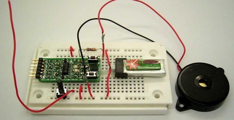
The microcontroller running the code is an ATtiny13 on a Sparrow board. He’s using an everyday LED as a detector diode and an internal pull-up resistor in the ATtiny13 for the bias voltage. The antenna runs off the LED’s anode. To make it sensitive enough, he switches on the pull-up resistor for a tiny fraction of time. Because an LED can act like a small capacitor, this charges it to a few volts. He then switches the pullup off, and the voltage across the LED will start to discharge. If there is an RF signal present, the discharge voltage will be less than the discharge voltage with no signal present. Neat stuff.
Be sure to check out his Hackaday.io page linked at the top for full source, schematics and some videos demonstrating his project.


Cool!
Wouldn’t this be affected by the parasitic capacitance between the antenna and ground (ground as in anything connected to the earth)?
Yes, thats why I keep the antenna very short. Also a longer Antenna will receive too much. Like AM radio stations.
As there was no Magic Blue Smoke I believe this circuit has no gremlinistic parasites yet.
“only a handful of components and thirty eight lines of code” WHAT
A simplest RF detector consists of two diodes, an RF diode and a LED. E.g. see https://www.youtube.com/watch?v=CNJVhzOjWgU
In reality you dont even need that special of a diode. In the day when nokia’s were all the rage they sold replacement screw in antennas with i believe just a 1n4148 and a led.
in physics class, we used a really small classic miniature lightbulb, and a mobile phone. also worked very well…
My Friend uses 1n4007, small cap and one of these galvonometer-thingies, works very well, and has ratiometric output…
oh, 1n4148, sorry -.-
In the world of ARDF there are maniacs who claim only LED is needed: http://ddwilliams.blogspot.com/2011/08/worlds-simplest-ardf-receiver.html
Don’t know if it’s real, although I know David and usually he’s not kidding around.
It’s actually an LED and a diode. Looks something like a 1n4148
“When [b.kainka] set out to make the world’s simplest RF detector”
OMG! He missed the goal by so much! How many millions of transistors are we looking at here?
“A simplest RF detector consists of two diodes, an RF diode and a LED….”
Warmer…. But.. No way is it the simplest. It’s not even close! What all sorts of rare doping elements went into those diodes. What processes are used to make those tiny little, nearly microscopic PN junctions with such precision?
This looks kind of simple:
https://www.youtube.com/watch?v=p4krVVwAkH0
Nope, that was complicated in comparison to this one:
https://www.youtube.com/watch?v=DX7cTJjqomg
But that’s not it…. The simplest radio detector is a friggin metal loop with a small gap in it! Sorry, I couldn’t find a Youtube video on that one so here is an informative web page. http://earlyradiohistory.us/1917de.htm
I’m sure that most aren’t here for the history lesson but seriously, how many present understand everything about how the microcontroler is built and works from sand on up? On the other hand what does it take to understand that metalic loops will have voltages induced on them by radio waves and that these voltages emit visible light when they are forced to jump a gap?
It’s nice to know about the really old stuff because it allows you to understand the foundations of how things work underneath the complexity even today. And.. once you do then certain claims about things being “the simplist” seem kind of rediculous.
Be sure to check out his website http://www.b-kainka.de/last.htm – use you browser’s or external translator – B-Kainka is well experienced and the ‘certain claims’ has been simplified in the HaD headline/post to miss the point – a mcu based detector (which could be used to implement the function in ultra cheap toys and gadgets.)
IIRC I have seen spark gap write ups in the authour’s site.
That was a little unsettling. I never expected to see a random video from a passed away fellow student when scrolling through HAD comments…
I know that a simple detector can be simpler. But the point was this. Using an ordinary microcontroller system, how kan one detect RF signals without any additional components.
The thing that bugs me most is that the LED is a lot more sensitive to light that the whole thing will be sensitive to rf, granted we are looking at different frequencies.
I bet the only thing he is picking up is signal through capacitive coupling. In fact, since the pull up is some 20K(tiny impedance for pickup), you could probably make a more sensitive detector by using a pull up/down resistor of larger value, like 10M.
The LED isn’t receiving anything. The antenna is.
The LED is just acting as a diode, acting as a rectifier. You’ll note he actually periodically turns on the internal pullup, to “charge” the diode – that’s to get over the voltage drop of the LED to the point where it can conduct and actually act like a rectifier.
A Schottky diode wouldn’t need the pullup as often (if ever) due to the lower diode voltage. Schottky diodes are often used as zero-bias RF detectors if they’re doped right.
I use a Schottky diode with a reverse mounted LED as a microwave (oven) leakage detector.
I once found out that a 1N34A had leads almost exactly the right length to act as a 2.4GHz antenna. Clip the ends onto a scope probe and use it as a crude RF field strength meter. Or connect a pair of high impedance headphones, put it up to an AP, and listen to the packets fly by. I also tried LEDs but the best I could get was a very dim glow from even a very sensitive LED.
I quite like my £2 433Mhz reciever directly connected to my £1 piezoelectric buzzer.
This is a great idea. It biases the diode right up to the conduction point which will make the detector more sensitive.
Uhhh… the simplest RF detector is only ONE component: A CFL bulb available at hardware store for less than a dollar in some stores. Try it in a RF field like a FRS/GMRS walkie-talkie or some other reasonably medium powered transmitter. And no Bill Sweetman Nikola Tesla did not invent FL’s. It is debatable whether he used a enclosed FL lamp and light-dependent resistor arrangement (as his tunable RF switch) or a already invented Branley Coherer (BC) circuit for his remote control boat demonstration for USG at MSG (NYC) in late 1890’s.The BC may be even simpler RF detector than a CFL. It only uses metal-oxide powder in a glass tube with electrodes on each end. You have to tap it after every use to reset. That’s why I don’t think Tesla used a BC due to the tapping reset requirement.
CFL (compact fluorescent lamp)
FL (fluorescent lamp)
USG (US Govt)
MSG (Madison Square Garden)
@Bill Sweetman – yeah I know you never mentioned Tesla. I just knew what you were thinking when you typed this up… (just kidding) :-)
how to connect cfl bulb to walkie talkie?
You just transmit next to it and it should illuminate before your eyes… no connection at all.. not sure what frequency works best. Frs is uhf. Around 400 Mhz.
how to connect the cfl bulb to walkie tackie? and what else you need to conver the
walkie tackle to a rf detector?