[esot.eric] was trying to drive a motor and naturally thought of using pulse width modulation (PWM) to control the motor speed. However, he found that even with a large capacitor, his underpowered power supply would droop before the PWM cycles were complete. So instead of PWM he decided to experiment with pulse density modulation.
The idea is to use smaller pulses over a longer period of time and make the average power equal to the percentage motor speed desired. With a PWM system, for example, if the time period is T, a 50% PWM drive would have the drive high for T/2 and low for the other half of the cycle. With pulse density, each pulse might be T/10 (as an example) and then the output would be on for 1/10, off for 1/10, on for 1/10 and so on, until by time T you’d still get to 50%. The advantage is the output capacitor gets a kick more often and has less opportunity to droop.
You probably want a scope to measure PWM or pulse density, but we’ve talked about how to do it scopeless before. If you want to go old school, think about how to do pulse density with a 555 chip and post it on Hackaday.io.


many digital mems microphones use PDM, this is real PITA to decode, at least some while ago the software libraries for the PDM used to be “binary blobs” or pre compiled libs not in source code..
It really depends, if you want to do purely digital processing CIC filter for example are a good way to process it.
And they are pretty well optimized for MCU/FPGA (no multiplier needed).
Its still PWM, just the off time only changes. Can be quite difficult to filter for EMC needs, plus you still need a PSU with some grunt at high “densities”. Ye canne change the laws of physics Jim…
It’s one of those things where I’d never thought I’d find a purpose in a *motor* driving application (due to heat generated during MOSFETs’ switching times, thus wanting the *fewest* transitions necessary… thus PWM generally seems a better choice)… but here it seems to be a good example.
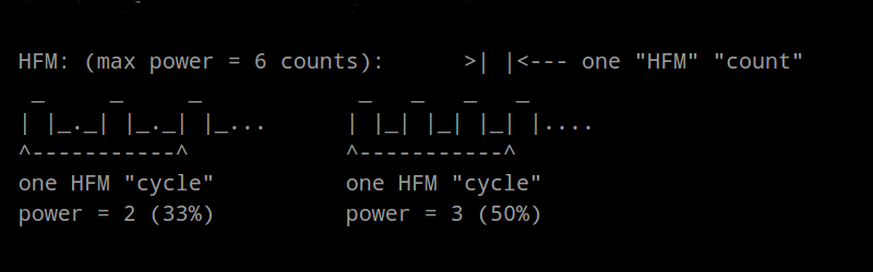
In my circuit I don’t intend to use more than 33% power, so two pulses never get butted together… the capacitor can be half as large as the case where I’d need 51% power (where two pulses would be butted together), and 1/3rd as large as, 67%(?) where three pulses would be butted together… But, obviously, if I was planning to use up to 100% power, the capacitor would have to be the same size for PDM as for PWM… (and my power-supply would definitely not be up to the challenge).
As far as electromagnetic-radiation, YES. That’s a lot of high-voltage/current switching… definitely would have to be considered in any product-design… and may interfere with your circuitry. Wee!
wait.. what?
Just because you define a cycle as a multiple of transitions doesn’t make it something else than PWM.. or does it?
What I see is just an decrease of the PWM period. Looking at each period by itself the relationship between high and low is still the same.
or is the trick here that the period time changes constantly?
I was just going to say the same thing… I guess you could do a multi-layer PWM (so the higher-level ‘on’ and ‘off’ are PWMs themselves – as used in some LED controllers), but it’s still PWM.
Yes, the period changes. PDM with a fixed period reduces to PWM.
It’s difficult to make that comparison… what about the case of 2/5ths power… In that case one cycle is 10100, so it’d be the equivalent of two back-to-back PWM cycles with varying frequencies and varying powers…
Yah.. To me, this is just bumping the frequency up a bit. (Also something you have to take into consideration at design time).
PDM to me seems it would be more like, for example:
A 50/50 duty cycle.
Within the ON pulse, you have another PWM signal.
Essentially an outer PWM signal at a lower frequency, and an inner PWM at a higher frequency.
I’m not exactly sure I understand this description, but it sounds interesting. It kinda reminds me of a potential use for the programmable-logic sections in some new PICs… e.g. AND two PWM outputs…?
“Just because you define a cycle as a multiple of transitions doesn’t make it something else than PWM.. or does it?”
Why would you call this pulse *width* modulation? You’re not modulating the width of a pulse. You’re modulating the number of “on” pulses (or ‘off’ pulses once you pass 50%) in one cycle. So yeah, calling it something else makes a lot of sense.
Obviously the effect is still the same – the DC content of the output pulse train is identical. The difference is where you’re putting the AC power, spectrally. At 50% power, for instance, an 8-bit ‘PWM’ implementation at 1 kHz period is a square wave of 2 kHz (128 bit times up, 128 bit times down). A ‘pulse density’ implementation is a square wave at 128 kHz. The 128 kHz square wave is probably going to be easier to filter.
How much benefit you get depends on where you expect to sit: if you expect to sit at 50%, this can be a pretty big boost. If you expect to sit at 10% or 90%, the difference is negligible.
This trick is pretty common in FPGA implementations because it’s stupid easy:
http://www.edn.com/design/analog/4318138/Swapping-bits-improves-performance-of-FPGA-PWM-counter
Some microcontrollers can do it in hardware too, if the timers are smart enough, although you often need to do something smart once you pass the 50% point.
very simple pwm in an fpga:
always @(posedge clk) {PWM_out,PWM_acc[7:0] <= PWM_acc[7:0] + PWM_in[7:0] + PWM_out;
Ah, hardware-based under 50%…. I can see it. E.G. on some AVRs you have two timer-registers related to PWM generation: OCRA and OCRC… the counter counts to the value in OCRC and resets. The PWM-enabled counter turns on the pin at the beginning of a count-cycle, then off when the counter reaches the value in OCRA. So, typically you’d set OCRC to a constant value like 255, to set your PWM frequency, and adjust OCRA to change the pulse-width.
But, something like PDM could be implemented by instead setting OCRA to 1, and varying OCRC… the larger value of OCRC, the smaller the power-output. Hmmm, that might be useful some day.
It is a bit more limited, in that it only has 100%, 50%, 33%, 25%, 20%, 1/6, 1/7… and so-on as options, but still plausibly useful.
This is exactly what Delta-Sigma does.
Here is an example, with compared waveform and an implementation algorithm: Delta-Sigma versus PWM
RoGeorge! I had every intention of linking your Delta-Sigma vs PWM project on that log entry, will do-so now!
I also had every intention of looking up the various names for it, Delta-Sigma, Pulse-Density, I think there’s another as well.
Al Williams, Thanks for the writeup!
Everyone: Seriously: RoGeorge has a great page relating to this!
I’ve also seen it called “pulse frequency modulation”. And as you’ve mentioned, it’s identical to first-order sigma-delta modulation.
So, Is PDM a PWM with higher frequency?
no, not at all.
for an audio take on it, search on DSD (which is used in sacd audio discs). dsd is truly pdm based encoding with the goal that the playback system is trivial, needing only a LP filter, pretty much. audio is encoded in varying widths of pulses so that the area under the curve approximates the analog wave, itself. its not a maths-heavy conversion like pcm is and the DSD audio files are starting to appear now that dsd-based dacs are starting to appear.
When doing pwm in something like an FPGA a variation of it is to bit reverse some or all of the bits in the counter
I think the article is not really explaining the difference, because when I read it, like others I thought all he did was crank up the time period for the PWM. T vs T/10 is only part of the story. Here’s the difference:
PWM:
Fixed Period
Increase on time to increase power (up to period)
PDM:
Fixed Time on
Decrease off time to increase power (down to 0)
Increase off time to reduce power
Accomplish with a 556 by setting one side to monostable with your fixed time on; trigger side one with an astable side two and change your total time period with a pot on the RC circuit.
“PDM:
Fixed Time on
Decrease off time to increase power (down to 0)
Increase off time to reduce power”
Not quite – you actually wanted “decrease off time to increase power, down to On Time period,” not to 0 (*). Then this is only up to 50%: past 50%, it’s a ‘fixed off time’, and you increase the ‘on’ time to increase the power. He’s not actually using past 50%, but the idea still allows for it.
It really explains it all in the name: you’re modulating the number (density) of ‘on’ pulses in 1 period if you’re below 50%, and number (density) of ‘off’ pulses in 1 period if you’re above 50%. Pulse width modulation modulates the width of a pulse in 1 period. The overall modulation period is actually staying the same.
(*: I guess you could go from 1 ‘off time’ period to 0 ‘off time’ period and never have “off time” pulses, but that would jump from 50% power to 100% power in one step.)
FFS – I’m still confused :-)
Pulse width modulation with value X: in 1 time period T, output 1 pulse with a width = X minimum time increments
Pulse density modulation with value X: in 1 time period T, output X pulses with width 1 minimum time increment
For pulse density modulation if X is too big – say, if you have a minimum time increment of 1 microsecond, and your period is 256 microseconds, and X is greater than 128 – the line idles ‘high’ and pulses are low.
The pulse train listing here:
http://m.eet.com/media/1128821/11861-listing_3.pdf
really makes it pretty easy to see.
Definitely check out RoGeorge’s link for a comparison… here’s his ‘scope image which is quite informative (hope he doesn’t mind my pasting it here):
https://cdn.hackaday.io/images/6463681435487156057.png
From https://hackaday.io/project/6356-delta-sigma-versus-pwm
That’s a wonderful image. I wasn’t quite getting the difference before I saw this.
I am mesmerized by the scope image and now I want to find an excuse to make one like it for a post ;-)
Wow, that is a super informative scope image.
This is true if he is using delta sigma like code and this is probably why he gets odd behavior at greater than 50% power, because he’s trying to make his time off less than the minimum time period.
Better definition:
Define one time period T as the smallest amount of time you can have an output on or off.
The cycle period then looks like an integer fraction based on the requested power.
Power = Time on/(time on + time off) and all numbers are integers
Examples:
75% = 3/(3+1) On = 3T, Off = 1T, Cycle = 4T
50% = 1/(1+1) On = 1T, Off = 1T, Cycle = 2T
40% = 2/(2+3) On = 2T, Off = 3T, Cycle = 5T (this is the smallest fraction for 40%)
33% = 1/(1+2) On = 1T, Off = 2T, Cycle = 3T (This is shorter cycle than 40% because it has smaller integers for the fraction)
The trick above is that the cycle time doesn’t vary linearly with the power, but with the complexity of the fraction.
I’m not sure if this is how others to it, but maybe simplify code by making your T much greater than the minimum and fixing it for motor control. Then you can adjust your off time to less than the on time.
Pseudo code:
Loop {
x = read pot;
Output hi;
delay 10;
Output low;
delay x;
}
In his case, he sets his on time to, say 10ms, and he has 1ms resolution, all of the available power levels are a ratio of 10/(10+x):
91% = 10/(10+1) On = 10T, Off = 1T, Cycle = 11T
83% = 10/(10+2) On = 10T, Off = 2T, Cycle = 12T
77% = 10/(10+3) On = 10T, Off = 3T, Cycle = 13T
66% = 10/(10+5) On = 10T, Off = 5T, Cycle = 15T
50% = 10/(10+10) On = 10T, Off = 10T, Cycle = 20T
25% = 10/(10+30) On = 10T, Off = 30T, Cycle = 40T
Of course, you get really bad resolution the closer to 100% you get, but you can counter that by using a log pot on the input, or coding it.
I’m learning a lot from these comments, thanks everyone.
I see two lines-of-thought here (in all the comments), regarding PDM. There seem to be two different implementations. One is what I’d call the “1/n” case… That seems to be what’s described here. Essentially: fit one pulse in a varying timeframe… on for one count, and off for (n-1) counts.
The other seems to be what I’d call a “n/m” case, as someone else described as “first-order delta-sigma modulation.” e.g. fit n pulses within (generally constant) m timeframe.
The latter is what I’m using, it’s not limited to a 50% issue, but I’ve never seen it in the form of a dedicated microcontroller peripheral (needs to be done in software).
Someone above suggested that some microcontrollers have it…? Otherwise, I commented above, the 1/n case could be handled with most PWM peripherals without much difficulty (interesting!).
And switching that polarity to get over the 1/2 -> 1/1 barrier is definitely a handy idea.
Have you considered binary code modulation aka bit angle modulation? It doesn’t do AS much to increase frequency, but it’s probably easier on code?
http://hackaday.com/2011/07/22/using-binary-code-modulation-to-control-led-brightness/
Never heard of it, but sounds interesting. Thanks for the link, definitely throwing it in to the ol’ bag ‘o tools.
I am writing to share my background and hope these comments will be taken positively. That is my intent.
I do believe the term Frequency Modulated is most appropriate. But yeah, the time average voltage delivered to the motor using this scheme should be similar to the power delivered via PWM and that’s why taking a dc level of the FM and PWM signal should be similar. Using a multimeter to measure the DC level of a time varying signal is equivalent to taking an average of that signal…in the lab. Don’t tell a Professor that :)
From the article: “Usually one would prefer a high enough PWM frequency that it wouldn’t be audible, >20KHz is preferable. But that’s not an option here. And, in general, there’s always an upper-limit to the PWM frequency due to switching-speeds of the motor-driver… Even motor-drivers that are significantly faster than the one I’m using. ”
20 KHz is not necessarily required and may not be effective. It depends on the frequency response of the motor being driven. What we do is model the motor/capacitor combination as an Inductive-capacitive (LC) tank circuit. That tank circuit will have an optimal resonance frequency at which power is delivered to the motor. However for frequencies significantly above that resonance frequency they may have the same effect as a DC voltage applied to the motor. So, if our motor/capacitor combination has an optimal drive frequency of 3khz, higher frequencies (20khz) may be effectively a DC level.
From the article:
“(TODO: Comments in the blog-entry suggest that PDM is actually used for audio encoding… should look into this)”
Yeah, it’s called a Class D amplifier. A TTL or LVCMOS level digital FM train is amplified and then filtered for audio output.
From the Article:
“In this era of MOSFET-based H-Bridges, most of the heat generated is actually generated during the time it takes to switch a MOSFET from full-on to full-off, or vice-versa. This is the time where the MOSFET is actually acting like a (large/varying) resistor, thus generating heat. Usually that transition is so quick most people won’t even notice it, but when switching *a lot* it becomes a concern. Note, because of that, HFM/PDM(?) is generally a *bad* option, because its main purpose is to switch at the highest frequency possible. Lots of (sloped) edges = lots of heat.”
The heat generated during MOSFET-based H-bridge operation is caused by charging and discharging the junction capacitance of the transistor. The power generated is modeled by the equation Power = ((1/2) Capacitance*Voltage^2)/Rise time + ((1/2) Capacitance*Voltage^2)/Fall Time. Rise time and Fall time can be on the 100 nanosecond scale…. Remember to use a current limiting resistor in series with your transistor gate or you may blow out the transistor with over current issues.
Lots of straight edges= lots of heat. The reason is that straight edges contain frequency harmonics that contain power and are dissipated in the circuit. From a purely theoretical perspective, if you take the Fourier Transform of a time domain signal (FM pulsetrain) the result will show the fundamental frequency as well as an infinite number of other frequencies at (2n+1) intervals. The motor capacitor circuit can be modeled as an LC circuit that has a frequency response. Frequencies tuned to that resonant frequency deliver the most power. Other frequencies (harmonics) are dissipated as heat. Think of it like an audio filter. This is coming from someone with a Radio Frequency background.
From the post:
“So, I intend to run the motor at no more than 33% power, using 12V and one of these modulation-schemes. That’s roughly the equivalent of running the motor off 4V.”
Although the average voltage may be 4V, I am somewhat concerned about the long term effects applying 12V to your motor rated up to 6V will have over time. Same goes for your power supply. Do you think it may be prudent to use a DC/DC converter to step down the 12V Power supply output to 6V and use the 6V to drive the power electronics? Max power is still limited by the power supply…. Just a thought!
Right on, thanks for the informational-foodstuff. Gonna take a while to digest, and certainly some intriguing thought-points for later consideration. Mind if I copy-paste this to the [b]log-entry for later reference and for others who might somehow mistake my ramblings as those from some sort of authority?
Yes, you are welcome to copy and paste. Feel free to give credit ;)