Over 750,000 people pass through New York City’s Grand Central Terminal each day. Located in the heart of the city, it’s one of the largest train stations in the world. Its historic significance dates back to 1913, when it opened its doors to the public. At the time, few were aware of the secret computer that sat deep in a sub basement below the hustle and bustle of the city’s busy travelers. Its existence was kept secret all the way into the 1980’s.
Westinghouse had designed a system that would allow authorities to locate a stuck train in a tunnel. There were cords stretched the length of the tunnels. If a train stalled, the operator could reach out and yank on the cord. This would set off an alarm that would alert everyone of the stuck train. The problem being that even though they knew a train was down, they did not know exactly where. And that’s where the computer come in. Westinghouse designed it to calculate where the train was, and write its location on some ticker tape.
So this is the part of the post where we tell you how the computer established where exactly the train breakdown occurred. Although the storyteller in the video is admirably enthusiastic about telling the story, our depth of detail on the engineering that went into this seems nowhere to be found. Let us know in the comments below if you have a source of more information. Or just post your own conjecture on how you would have done it with the early 20th century tech.
The invention of the two way radio made the whole thing obsolete not long after is was built. Never-the-less, it remains intact to this day.
Thanks to [Greg] for the tip!


Measure the resistance down the rails is all that springs to mind.
That would be tricky with multiple trains in on each track. I bet you could set up the equations to produces a candidate set of locations, but this beyond the capabilities of the time I think…
I mean you know what rail you are on due to the bells but not how far down the rail.
The R&D group in my university had a spice type of simulation program (probably in FORTRAN) to calculate the complex impedance with the trains loads at various points on the tracks, transmission lines and the feed.
Worked at company in the 1970’s that made crossing predictors that sent a signal down the rails and used the rate of change in impedance to predict when a train would approach a crossing. This unit was a cross between an analog and digital circuit.
That was my thought too. Perhaps the cord the operator pulled in the tunnel simply indicated which track and the resistance was supposed to calculate distance. With multiple trains using the same track are they electrically isolated so they can test it in sections?
That’s how modern railway systems work. These days there’s even bi-directional communication along train blocking, I’m not sure for early 20th New York, but considering density of everything I guess the metro would have been useless if it wasn’t for proper signaling.
https://en.wikipedia.org/wiki/Track_circuit
Something tells me Tesla invented it and Westinghouse tried to steal it.
I think you mean Edison, not Westinghouse.
The railroad’s interlocker (their version of air traffic control) would already know where the trains are. Its job is to ensure the signals and turnouts are operated only in a safe manner. I suspect that the cord was just the “I’m in trouble” signal which would make the machine retrieve the information from the interlocker and print it. You can see a video of the Grand Central Terminal interlocker here https://www.youtube.com/watch?v=xRWdjegF618
That’s cool! Thanks for the link.
Item for another article (vaguely related) is how the Bell System detected and calculated distances to breaks in their lead jacketed, sawdust insulated, pressurized trunk cables.
A TDR can do that. https://en.wikipedia.org/wiki/Time-domain_reflectometer
On long-line phone cables, well before TDR, they would check the impedance in the line. The story I got from the Pioneer Telephone Museum was that if the Bell engineer was more than two poles off from the fault he would owe the lineman a beer.
Oh, that (the beer thing) sounds about right for engineers and linemen. There’s professional pride on the line there.
Another method for detecting a break in a multi-core cable: choose a non-broken wire and measure the capacitance between it and the broken wire measured from each end.
If all conductors are broken, measure the capacitance of a cable of similar length.
You can estimate the location from the ratio of capacitance.
Start with an Arduino …
Reminds me of the short story “A Subway Named Moebius”
And here I was the best Argentinean Sci-Fi movie I ever saw (sampling bias may apply) was an original story…
http://www.imdb.com/title/tt0117069/
That is a very nice movie. With “Carnagui” :) none the less. They produce some fine movies from time to time…. missing home again…
You should watch “Hombre mirando al sudeste” :)
A great story. Read it back in the 60’s. By A.J. Deutsch and the Good Reads synopsis:
“When the MBTA (Boston’s Public Transportation authority) introduces a new line, the topology of the network become so complex that a train vanishes…lost in some fourth dimensional properties of the network.”
Actually getting two way radio to work in tunnels isn’t simple. Radio Waves don’t like tunnels. You need either a “Leaky Feeder” or “DAS” (Distributed Antenna System).
The guy also says its “electronic” but it looks more electrical to me with Relays as the active components. would guess it uses the block signalling system to know where trains are. Track is divided into blocks a few hundred feet long. Only one train is allowed in one block. Short sections of isolated track are placed at the entrance to each block. The train wheels short the rails in this section and allow the system to detect trains traveling between blocks. All you need is one bit of pull chord per block. More info on the signalling system is here:-
http://www.nycsubway.org/wiki/Subway_Signals:_A_Complete_Guide
The London subway system used a simpler system. There used to be a par of copper wires running along the tunnels and each train had a phone set with a pair of crocodile clips. Just clip it to the wires, ring the signal man and tell them where you are and what is wrong…. (note Signalmen may be female…)
Signalperson?
Signaller!
The speed of sound may have been
involved
My bet: the line the operator pulls closes a switch. and this simply earths a wire under a certain voltage. Next halt: Ohms law, Job done.
If they used knicker elastic for the pull cord and told the driver to hold it firm after he rang it then when a bell went off at this end an operator could pull the cord until it didn’t stretch any more and the stretch would tell you how far the guy holding it was away. :) Did they have knicker elastic back then?
I doubt they did it that way but it is a solution. :)
First, I think we need to consider early *20th* century tech, not 19th.
The resistance of the pulled cord could be measured by a Wheatstone bridge. There were printing recording wattmeters by 1907, so a printing ohmmeter by 1913 would not be a stretch. One could also use a source of data as Dave Wade notes (a pull cord for each block) that would send a code down a wire. That is actually how many existing stock-ticker protocols worked: operators would press keys and the sending terminal would send code (not Morse, but custom for each manufacturer) down the wire representing keys pressed.Perhaps sending a “Q” code meant a particular segment or block of track.
I was thinking the same thing – I bet the pull station is sending a code.
I have an old mechanical fire alarm pull station that works on a similar principle. When the handle is pulled, it winds up a spring and a coded cog rotates against a set of contacts sends that code out the common alarm bus wiring. Simple encoding, eg ‘—– — —‘ for station 523. It repeats several times until the spring relaxes:
https://en.wikipedia.org/wiki/Manual_fire_alarm_activation#Coded_pull_stations
So, for this system the alarm receiver system could latch the bell on, enable the ticker, and print the code. When the operator hears the bell, they’d reset the alarm, decipher the code on the tape and do whatever it is you do to dig out a busted up train.
Honestly, if the engineer could reach out a window and pull a cable, wouldn’t it be just as easy to have distance markings painted on the wall, and make the pull cable a wire with regularly spaced jacks that would allow the driver to plug in a Morse key, and simply tap out his location?
Would there even need to be plugs? It seems he could just have clips; one to the rail and the other to a wire.
If it was built into the cockpit, it could ground through the wheels, and only clip 1 wire…
Or if they can reach out and pull a cord, and know where they are, they could be allowed to pull Morse code on the cord directly (don’t latch the bell on) to indicate their location.
this was my vote
Trains subdivide tracks into blocks of certain lenght as a safety system and only one train can occupy a block at a time.
Maybe instead of telling the exact position of the train in the tracks using some black magic, each block had a pulse generator tied to the cord of that section.
Each block could have it’s own code as a cuantity of pulses (quite simple) and the computer tied to the line just had to count those. Blocks usually only measure 1000 or 1500meters, so once you know the block, finding the train just requires minutes.
I’m thinking one of the rails is split into insulated segments, and the other is continuous. The whole thing seems to be relay-based, so all the insulated segments could act as inputs to the relay logic and when shorted by a train to the continuous rail, would indicate train presence on that particular segment…
I would say every mile or so, there would be a resistor in line the tracks, and then the train would connect the left track to the right track, and all you would have to do is send a current bown the tracks and measure the resistance
probably like the duck hunt game, one wire on the wall pulses on momentarily while traveling near the speed of light like the scan line on a monitor. the rope activates the light gun trigger that detects the electrical pulse and passes its on state to a second wire on the wall. the computer uses the timing difference between the two to calculate the length of conductor and thus the location of the train.
I think a time domain reflectometer requires parts a bit faster than relays…
You may be able to be very clever and measure the phase difference with a special ac galvanometer (I don’t know if they make those, but it would have two coils, like a universal motor) but I doubt that’s what they are doing, as everything would have to be very high frequency, which would be hard for a sensitive galvo, and could also be hard to make electromechanically.
My guess, like others have said, is using a wheatstone bridge to measure cable impedence, with the relays just being there to operate the printing mechanism and alarms.
They may be able to use a galvo attached to a character plate listing distance that gets struck by a hammer to make the distance printing, but again, I am just guessing.
Maybe each tunnel had two ropes going in on either end and meeting in the middle.
That way you can tell in which tunnel the train is and which end is closest.
Or maybe there was a new rope every 100 meters that would activate a number of relais to send a binary code to the computer.
Or maybe each rope would activate a musicbox like device that would telegraph it’s location to a tickertape machine.
Perhaps there was one 66 mile rope snaking through the tubes with 33 miles rolled by the computer.
It would be marked in the middle and the engineer would keep pulling the rope until he had the mark in his hand.
The computer would then output the value of an odometer attached to the rope.
What restrictions are we under when speculating about how this computer worked?
What technology (existing at the time) can and cannot be used?
How accurate was the data coming out of the system?
I like the 66 mile rope idea.
Pretty hilarious. XD
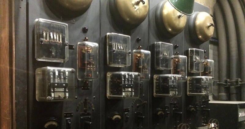
I worked for Westinghouse on the Bay Area Rapid Transit (BART) system in the late 1960’s. The system that all railroads use, and have for decades has been what is called a “Block” system. Trains are detected within the block, and that is as close as the system gets. This lets train traffic signals know what speed other traffic can go as it approaches other trains. If one is broken down, other trains near the block that contains the broken down train are brought to a full stop. Seeing the picture above reminded me of the “Failsafe” system that I saw at each station, that changes the signals. The bells were not part of the system.
It may be semantics, but not all tracks are detected in blocks – in dark signalled areas, the only train detection is around level crossings. And there are some damn fancy strike detection algorithms that detect where the train is and how fast it’s going so they can activate the crossing at the right time.
It’s not very often my career gets mentioned on the internet, people usually think trains just work and ignore signalling as red/yellow/green when it is so much more!
It has always been a mystery to me how the gates know when to come down — and when to go back up again, and when to stay down for the train coming from the other direction. “Pretty damn fancy” was about my conclusion.
The line by my house has capacitors between the rails periodically. This, and the impedance of the rails, makes a resonant circuit which changes in frequency when the raila are shorted by a train.
Sometimes, there are notes near the capacitor, like “27uF, 344Hz, 1183′ to Main Street”.
Before that, there were insulated track segments near crossings. When a train wheel would shorts it out by rolling across it, the gates would go down and stay down with a timeout.
Only in America do we over complicate everything. during the space race, we spent millions to design a pen that would write in no gravity, the Russians just used a pencil.
NASA did not develop the nitrogen pressurized pen, it was developed by a pen company independently and it’s potential for space use was seen. Pencils also have the issue that they particulate heavily, spreading conductive dust around.
I’ve wondered if NASA or the Russian Space Agency ever bothered to test an ordinary, cheap ballpoint pen in microgravity?
I’m not too sure why capillary action would be affected by the presence or absence of gravity.
In a vacuum, perhaps the ink might evaporate out the back of the tube reservoir found in the cheapest pens.
Other than that, it just seem likely a good marketing slogan “as used by NASA”.
I think when the pen is upside down or in no gravity the ink in the tube moves too far from the tip for capillary action to matter. I don’t see what could cause the ink to move like that in zero gravity though (maybe surface tension or capillary action up the tube?) unless it was oriented poorly during acceleration or spun.
I’ve read that the favoured type of pen on the ISS are the cheap ballpoints found in the European Space Agency offices.
They used grease pencils to avoid the issue with shavings. Specifically, both NASA and russia used grease pencils
But when it comes to train, have you ever heard of Shinjuku Station…
Measuring the resistance of the rails is great, so long as the problem isn’t the train derailing or the track broken.
I would put a momentary reed switch or pressure switch under the rails in every mile that each will trigger a relay flip flop circuit to the station as the train is passing that will power on a light bulb on a panel that will indicate the train’s position on a map.
When a train will go the opposite way the system will indicate its position on the map as good by turning the lights off instead of turning them on.
If the train fails to make it to the next mile an operator would be there to notice that something is going on and they will try to communicate and send help.
We don’t care about power loses and consumption as we are in 1913,we also don’t care about calculating anything unless it’s about estimating the trip’s duration.
I was thinking about a system where the cord is suspended from a lever at both ends, the lever is attached to a variable resistor possibly geared or balanced. pulling the cord would deflect each lever a different amount based on distance. more deflection the closer as more of the force would influence the closer arm more. Then do a voltage divider version of a a/d conversion and calculate the trains distance from the two ends.
If I had to do it in 1913, I think I’d run a pair of signalling wires down the length of the tunnel. Call one “Source”, and the other one “Sense”. If the train breaks down, the Conductor shorts and the The Source wire is grounded at the Start of the tunnel, and connected to a known voltage at the End of the tunnel. The resistance of the wire establishes a voltage drop along the wire proportional to its distance from Start.
When there’s a problem, the conductor shorts the Sense wire to the Source wire. This puts a voltage on the Sense wire that tells you where the train is. The Sense voltage can just be read with a voltmeter that is marked in distance.
Many variations of this technique are possible.
I would imagine could be like a rotary phone dialer (which was new technology at the time.) Yank the cord and it would retract sending a number of or combo of pulses. the ‘computer’ would them count these up and output a result. Just speculation…
Something to do with time it left the station and the average speed until the reported stop?
McCulloh loops were used by Western Union and for alarm systems to provide unique location coding for an event. The W.U. subscriber would turn a spring return knob which, through a clockwork escapement and cam, operate a pair of contacts which would open and close the contacts in a pattern assigned to a particular location. Upon receipt of a signal Western Union would dispatch a runner to retrieve a handwritten message from that location’s subscriber to be brought to the W. U. office for transcription and subsequent transmission via telegram.
In the alarm industry a leased drop line was required from the subscribers’ locations through the telco central office to a central monitoring location.
The successful lawsuit against ATT by an answering machine manufacturer (Codaphone ???) opened up the attachment of “foreign devices” to standard voice lines and introduced the voice dialer to the alarm industry which started the demise of the McCulloh loop.
Apparently some of these systems are still in use. (http://www.mccullohfire.com/)
I retrieved several of the W.U. subscriber call stations from abandoned buildings in the ’70s.
a.k.a. “current loop”, just like the old Teletypes.
They are probably the same. The McCulloh loop (as the security industry called it) was capable of sending alarm signals under many fault conditions. According to this article, http://www.dgasecurity.com/about-dga/alarm-industry-history/, it dates from the 1880’s.
The circuit is described in detail on page 527 of “Journal of Electricity, Power, and Gas, Volume 33” dated 1914. (http://tinyurl.com/ptgb5n)
1913… It was resistance or multiple wires with switches… No question about it..
It’s basic engineering and I’m not sure this is a computer..
I’ve been researching this for a few hours now (love retrotechtacular!), and I’ve come to believe the system isn’t based on resistance, multiple wires or blocks of track.
Resistance would be quite a hassle to get right, especially given the enormous distances and the questionable metallurgy / insulation knowledge of the time. Blocks of track, where the axles of the trains function as conductors would not have worked, since the system would stop to function if a train derails. Solutions like storing the last known location would require (for the time) inconceivable amounts of memory. Besides, both of these systems would need a lot of (at the time) very delicate components that would have to be maintained very regularly.
Multiple wires with a single wire representing a section of tunnel would work, but there was a better system available at the time. As early as 1870, spring-loaded pulse dialers were used for signaling jobs like this. There were fire alarms, burglary alarms and even convenience services using these. In fact, ADT (Apparently a big company in the USA) has it’s origins in this technology, providing burglary alarm systems based on these dialers.
By 1913, this would have been a well tested and proven system. In fact, some of these devices are so reliable, they are still in use today or have only recently been replaced. It would have been the obvious choice for a system like this. A pull on the cord activates the dialers (and may have even replaced the spring in these devices). The coded signal is received by the ticker tapes and the bell rings.
http://today.slac.stanford.edu/feature/2010/fire-alarms.asp
https://en.wikipedia.org/wiki/The_ADT_Corporation
https://books.google.nl/books?id=vKoXAAAAYAAJ&pg=SA2-PA28&lpg=SA2-PA28&dq=McCulloh+fire+alarm&source=bl&ots=keY4WQWTe8&sig=3Aa-ret5RxSoZ_L90BNgNlFuueQ&hl=nl&sa=X&ved=0CB8Q6AEwADgKahUKEwiahuPF9MzIAhUDjSwKHbxeBMo#v=onepage&q=McCulloh%20fire%20alarm&f=false
That would also explain why this “computer” barely has any components. That’s simply because it’s not a computer, it’s just a receiver. These pulse dialed systems needed ticker tapes because the signal was only sent a limited number of times before the spring ran out of tension. And that’s exactly what we see: ticker tapes and some switching components. Nothing more, nothing less.
Only just realized: The relays are probably just to trigger the bell(s) on receipt of a coded signal by the ticker tapes.
One of the images in the article is showing a box with “visicode” and “supervisory control” written on it. Google searches with those two terms point to some kind of low-speed serial protocol devised by Westinghouse.
However, this seems an awfully complex protocol just to locate trains. I’d imagine these machines were used for more than just that.
I was a Rail Network Controller for quite some time, and each route was seperated into ‘sections’. Each section measured resistance over the rails to see where trains were. Even up until 2013 our country was relying on knowing where a train was within 1-5km (what each section was).
Our rules as Network Controllers was to never EVER route trains so that two would enter the same section at the same time. If they did, all sorts of alarms would go off in our end exclaiming there was a collision. All the driver saw was a red light indicating to stop. Then lots of yelling over the radio, and a driver that when he got the alarm expected to be either rear-ended or head-on collision. Our drivers knew their overall route, but were only directed as far as the next section.
This is doubly terrifying when it’s single rail and 2-way. the driver had to trust that I had not routed an incoming train into him while he was not in a ‘station’ or crossover.
I will tell you know, it was the most stressful job I have ever had. Working on a old DOS based reconstruction of your route and any mis-click could end in deaths and possible imprisonment of me for manslaughter.
Kind of like air traffic control, but with a DOS computer instead of a radar screen, huh? I got tense just reading those last paragraphs.
Yeah it was a stupidly stressful job.
We also had to manual log each trains position on a piece of graph paper roughly 1.5 metres wide by 60cm high.
This was do to translate where we WANT the train to go and where it ultimately ended up due to whatever reason (cow on tracks, frieght truck stuck on rails etc). So not only were we using the computer over perhaps 3-4 screens depending on the route you looked after, but you had to talk to every train on the radio, talk to track crews on the phone that could ‘just appear’ then reroute. Then translate all that information in different coloured pens and pencils in real time.
When things were OK, it was a breeze, just draw a little line, click a train into a section and have a coffee. But when something went wrong like a SPAD (stopping past a danger) or a driver fell asleep, your day was ruined. And you HAD to have your papers in order for archiving. I could walk upstairs and pull out the paper of the day a big accident occured up to 15 years ago if I wanted to do a incident report analysis.
Add to the mix, diesel and electric trains, plus my area of control was very volatile chemicals plus livestock and people. The PUBLICLY made statement on safe passage was ‘2 legs, 4 legs, no legs’. But it was actually the opposite. Get the nasty stuff out of here, get the livestock to their slaughterhouse quickly or else face possible dead produce, and people are used to waiting.
The tech is low, and works as intended, a driver trusts his controller with their lives, and any extra layers of tech in the way confuse them I’ve noticed.
Somewhere on a HDD I have a copy of the training VM image. It would be fun to break it out again.
And for all the trainspotters – yes we had scale trains in huge rooms that’s I could control like real ones.
Wow, this is fascinating. On reading other comments I was about to say “no way there isn’t some sort of redundancy, surely they aren’t trusting people’s lives on a human’s possibly-faulty awareness”. What do I know…
Thanks for that, it was informative. Would you know of any articles/pages detailing the job further?
The training image, I’m assuming it’s private and non-sharable? It sounds really interesting.
Contrast that with one of the newer AI system for Hong Kong subway
https://www.newscientist.com/article/mg22329764-000-the-ai-boss-that-deploys-hong-kongs-subway-engineers/
It’s unfortunate that there isn’t more technical information in the article. But I agree with Nijntje, this was probably an automated pulse code system. Calling this a computer is ridiculous. It’s not electronic either, it’s electrical. But regardless, it’s still rather cool. I’m a sucker for retro-tech like this. I have a lot of my father’s old electrical and electronic parts that I’d like to use in some sort of retro project some day.
I vote TDR as mentioned by tekkieneet, or pablo’s suggestion of semi-accurate RLC measurements, going on similar stuff in the telecomms industry (which tends to have a lot of cross-propagation with other utlities, tech-wise) they’ve been fault finding that way since the telegraph was invented.
“Measure the resistance” is really far too basic IMHO, rails (or specifically, all the joints / discontinuities / other stuff touching them) are going to be very unreliable as a “pure” resistance to tally up ohms:miles, again in my experience with copper & fibre cables you can’t infer diddly from a resistance/loss measurement alone other than open-circuit or short is probably bad.
TDR is an interesting, but the *idea* wasn’t around until the late 1930s (and was related to geology) and the modern form is post-WW2.
That should be “an interesting thought”.
Just purely a guess but could they use differential pressure on each side of the rope to pin point the spot where the rope is pulled.
Waves traveling down the rope would have a considerable time difference. Wave arriving at end point would operate a pair of hallway circuit switches. First switch would engage ticker tape, second switch would stop ticker tape. If tape moves one way, pulling was closer to one end, if tape does not move (only punches), rope was pulled in the middle, if tape moves the other way, pulling was close to the other end. Sort of like a delta printer in 2D. Length of line on tape indicates distance from the middle of the line.
it would be a simple, just send a pulse and time the return, just as radar, this would be in the black bible which was written 5 years prior to this and is the basis of radar today. the ticker tape is the timing as it would punch only when it got signal but still move and then measuring the tape between punches would give the time which could then convert to distance.