Comedian Demetri Martin does a bit about the phrase “sort of”. He says:
“Sort of’ is such a harmless thing to say… sort of. It’s just a filler. Sort of… it doesn’t really mean anything. But after certain things, sort of means everything. Like… after “I love you”… or “You’re going to live.”
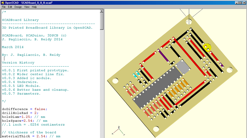
SCADboard is an OpenSCAD library that lets you create 3D printable circuit boards…sort of. The library lays out like a breadboard with two bus bars on each side and a grid of rows and columns. OpenSCAD modules provide a way to create a board, ICs, LEDs, wires and other fundamental components. You set a few initial variables (like the board thickness) then your code looks like this:
 wire(1,bln,1,e, neg); // Neg left trace to LED
 led(1,e+1, 1,e+2, yellowled); // LED
 wire(1,f, 1,i, pos); // LED Pos
 wire(1,j, 1,brp, resistor); // Resistor

 wire(3,c,3,h, pos); // Cap Pos
 wire(4,c,4,h, neg); // LED Resistor
The catch? You can print it, but there’s no electrical conductivity. There are little troughs for you to include wires. The authors suggest you twist the wires together. You can solder them, but if you do, you have to be careful not to get the plastic board hot enough to melt. That might take a little technique or some heat sinking. It certainly requires a steady hand and fast soldering. We thought about covering the printed substrate with Kapton tape and punching through it to pass the wires through holes, but we aren’t sure how well that would work in practice.
Apparently, though, it does work. They did a layout of a simple Arduino board as a proof of concept. It is a circuit board…sort of. [Brian’s] been doing his series on making a PCB in everything, but we doubt this will make muster. Then again, you don’t really have to make them at all anymore.


Why not print over a standard prototyping multi-hole fiberglass pcb? One side could fill up the holes and the other could be machined to eliminate excess copper…
Fill the troughs with a conductive paste?
What about using conductive filament for the traces on a dual colour machine? Just load one extruder with conductive filament, and load the other with a non-conductor (PLA, ABS, PETG, etc…). A little cad work would generate an inverse of the board file for the slicer, and there you go, a fully 3d printed circuit board, at least in theory.
I haven’t looked lately, but last time I checked “conductive” filament was not terribly conductive. It was more like a printable resistor.
I was actually thinking of a copper/PLA mix filament that I read about, http://www.thevirtualfoundry.com, it’s described as 90% copper/10% PLA, ment for making copper statues with a 3D printer, but I don’t see why it wouldn’t work for making a circuit board.
Yeah I just wrote about that. I thought I read somewhere, though, that without the firing, it wasn’t very conductive. I might be confusing myself with something else, though. Now there is plenty of conductive ink out there.
It is conductive… Sort of
There seems to be a few issues with the picture on top of the article : a couple of red and black wires are touching.
No problem if the wires are insulated.
So you can print a piece of plastic that resembles a circuit board but doesn’t work like one?
Doesn’t sound very useful at all, in my opinion.
Maybe it’s the electronic equivalent of “fake food”?
I have printed some times fake electronics boards. The aim was to make a quick sanity check before committing them to the fab house.
It’s often easier (especialy for noobs) to have a substrate for what would otherwise be a free-form circuit. Doing this with a printout on cardboard is a great old trick. Print out the sheet, insert the parts, tie the leads together, maybe touch some solder, and done.
This looks to be in that vein, but 3D printed, with more structural support. It sounds like fun, honestly.
So if it’s not a circuit board is it a dead-bug or wire-wrap jig?
I was hoping the result might be a bit more 3D. A free-formed shaped PCB could be very useful.
Welcome to the world of rigid-flex PCB design. It has some benefits and some disadvantages. But for some products it’s really a game changer. To my knowledge there are not that many tools out there that fully support the design of rigid-flex circuits boards and allow you to work out the 3D aspect in the same tool. I just know that Altium Designer and Mentor Xpedition can do it pretty well. A flex-only PCB with non-flex components soldered to it is definately a NoGo tho. Solder joints and components will get damaged under the stress of bending forces. It’s already a problem with normal FR4 PCBs that you can crack components if you bend your PCB too much. (Happens a lot with ceramic capacitors near the board edge, if the boards are v-scored and then broken out of a larger production panel after component assembly and soldering).