Almost exactly four years ago, we came across a really neat module for sale on SeeedStudios. It was a $5 WiFi chip, able to connect your microcontroller project to the Internet with just a handful of wires and a few AT commands. This was the ESP8266, and it has since spawned an entire ecosystem of connected devices.
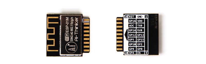
Now, there’s a new version of the ESP8266 that simply showed up on the Seeed website. Officially, it’s called the, ‘ESP8285 01M Wi-Fi SoC Module’, but you might as well start calling it ‘the Pluggable ESP module’. It’s the smallest ESP8266 module yet at 18mm square, and this one is designed to be plugged into a card-edge connector. It’s eighteen pins of wonder and 1MB of Flash, all ready to be stuffed into the next Internet of Things Thing.
The documentation for this module is sparse, and there isn’t even a mention of it on the AI Thinker website. That said, we can make some reasonable assumptions about what’s going on in this chip and what it can do. This module appears to be based on the ESP8285 SoC. Basically, it’s an ESP8266 with built-in 1MB SPI Flash. There are a handful of GPIOs available, and you should be able to build anything with this module that you could with other ESP8266 modules.
The highlight here is, of course, the card-edge connector. This is a module designed to be dropped into an existing product. You can program the module before hand, and assembly is a snap. The problem, though, is sourcing the relevant connector. It doesn’t look like Seeed has bothered to put a link to the right connector in the product description, although sourcing it shouldn’t be that much of a problem. The only question is if the card edge connectors on this module are hard gold (for multiple mating cycles) or just ENIG. Either way, if you’re plugging these modules into connectors dozens of times, you’re probably doing something wrong.


I’m impressed. No really. But how did you write all of that surrounded by 2 million hungry and purring tribbles? [See Mike S’s remarks concerning DEF CON badges and why they descended on all of you.]
*Three years ago
When will Brian adopt a new psuedonym to get away from this poking and prodding?
Has he already?
Has he left the bench?
If you ignore him, he will go away.
From the data sheet found at: http://espressif.com/sites/default/files/documentation/0a-esp8285_datasheet_en.pdf
The ESP8285 integrates Tensilica L106 32-bit microcontroller (MCU) and ultra-low-power 16-bit
RSIC.
It’s the 8266 and a SPI flash in an MCM.
I’ve hunted for a while and not found a connector. No doubt it is just a matter of knowing what specifically to ask for in the search bars.
The espressif site is unhelpful, saying they are easy to find. An actual link would be good!
It definitely seems like a odd dual edge connector. The male connector part of the PCB is rather short and seems like kind of an odd-ball pitch between contacts to me. (By the way, this is Ai-Thinker’s board design, not Espressif.) Ai-Thinker’s datasheet erroneously calls it a “DIP-18”, but it’s a dual edge connector, not a dual in-line package connector. https://www.google.com/search?rls=en&q=site:ai-thinker.com+%22ESP-01M%22&ie=UTF-8&oe=UTF-8
Digikey carries this TYPE of connector, if you can figure out the board height and pin pitch. I think the right category is ‘Card Edge Connectors – Edgeboard Connectors’
Maybe something like part no. HSEC8-109-01-L-DV-A-L2?
Vinalon: HSEC8-109-01-L-DV-A-L2 wouldn’t work; it has a pitch of 0.031″ (0.80mm).
Hardly the smallest. It’s rather large: http://www.esp8266.com/wiki/doku.php?id=esp8266-module-family
It does appear to be the smallest ESP with a etched PCB antenna. Oddly enough in that list is a compeditor’s part WT8266-S1 which is even smaller. So yay competition I guess. Just weird reading an ESP community wiki and seeing something that is some other company.
how is a card connector better than standard pin connectors?? the best interconnects are the most widely available :)
I’m not sure this is the best idea. There is no locking into the socket like with ram modules for example, and it’s going to be “flapping about in the breeze” in a short card edge connector which looks to be all of 3mm deep at best.
1MB is a bit small “to build anything with this module that you could with other ESP8266 modules”. I use 4MB ESP8266’s
If the PCB is thick enough then it could be wedged into a 18 DIP PIN header instead of a socket. Or perhaps you could solder it to a DIP header. Not very breadboard friendly unless you use one side and loose most of the GPIO.
I am waiting for comments on forums like GPIO4 and GPIO9 don’t work anymore.
Thanks for the heads up [Benckoff] .
[Benckoff][Benchoff] … typoMy bad, the pin spacing is only 1.8mm and not 2.54mm so it’s only good for soldering wires to.
1.6mm actually, which seems an odd choice (other than being the pin spacing for HDMI connectors) – I thought it might be designed to plug into a HDMI socket at first, but no, they have 19 pins, not 18, and are offset on the second side. Shame because piggy-backing on a standard like that would have been a neat hack in it’s own sense.
Glad to see you back!
Don’t worry about me; I’m taking a HaD vacation until I’ve got something worthy of posting. Life’s getting busy over here.
…bye for now. ;)
A pin header is definitely cheaper than a card edge connector. This module is probably intended to be soldered into a slot on a PCB.
That was my first thought. They look ideal for that.
This makes the most sense https://i.stack.imgur.com/Ep3mr.jpg
Sure, no connector is cheaper than any connector in mass production,
and by being vertical, the main pcb does not shield the antenna
Ithink this indeed makes themost sense. Why have a small ESP module and then waste the space saving on connector space. The advantage of using a slot into the PCB (as shown in the image as attached by Erik Johnson ( https://i.stack.imgur.com/Ep3mr.jpg )) then not only max amount of PCB space is saved also the integrated antenna is much easier to keep free of conductors all around. Because in the current ESP designs, the integrated antenna is always flat on the surface of your own PCB and no conductors may be close to that antenna. Simply because conductors close to this PCB antenna may affect performance and therefore the ESP-12 design for instance slightly limits the routing on your PCB. So keep the area close to the antenna clear of copper, which is pretty normal although I doubt that many of the ESP users are aware of and practically, the performance of the ESP is so good, that in most cases… it doesn’t ever matter. But still…
So anyway, this design is a huge space saver in many ways, and with so many soldering points this PCB will be stuck to your PCB like… well, just perfect. And it is easy, quick and cheap just like any other through hole component.
To be honest, I’m slightly disappointed in this Hackaday item that they did not mention that.
Because be honest, all other ESP modules (like the ESP-12 series) have a similar setup (no connector, just solder to your own board). But for some reason (perhaps because it is double sided) it is automatically assumed that the 8285 does require a connector. There are single sided connectors to… or might that be a surprise…
What really annoyed me is that Seeed (a company selling these devices) is put to blame for not showing a suitable connector… sorry Brain… do your homework before you accuse, as there might be a reason for this!!
So I guess that a “sorry” to seeed and a proper rectification of this article is appropriate, before this horrible “confusion” spreads!
If you read the comments section on Seeed’s site (at least yesterday), they were actually “looking” for a connector vendor so it’s not clear to me that Seeed understood how this module is supposed to mount.
Anyway, this kind of mounting is pretty common in super cheap consumer goods. They keep the “expensive” multilayer board small and use some crap one-sided copper on CEM-1 for the rest.
I think the ‘connector’ socket is really meant for manufacturer jig use.
So the module gets stuffed into the jig, programmed/tested/etc., then pulled and passed on – perhaps even to a different assembly house, such as a low skill, high volume type (in keeping with your last paragraph).
I can only assume there will be a huge influx of hastily assembled, super cheap, ‘Internet of WallSockets’ in the coming year.
> The problem, though, is sourcing the relevant connector … although sourcing it shouldn’t be that much of a problem.
Beforehand is one word, and before hand is some reference to some event called ‘hand’.
“Before [the issue at] hand”
Why use an at least Mini PCI Express connector, and use the standard pinout when applicable?
I have designed a LoRa pcb that will slot into a MPCIe and as USB in the right place, so plug it in a laptop and use it..
Because this module doesn’t have any of the interfaces present on MPCIe, and because MPCIe connectors aren’t convenient for hobbyists to work with. It’s far easier to hand solder a castellated pad module like the ESP-12 than MPCIe.
An interesting development. I don’t see this package as a ‘hacker’ part; this is something aimed at production, where it’s either soldered in, or a socketed option. It would also be simpler for programming the boards for small production runs (a programmer with a socket instead of a pogo pin fixture)
when this appears from a US source and has reasonable shipping, I get a few modules.
was going to get some now but shipping is absurdly high and not even very fast.
https://hackaday.com/2016/06/21/espressif-releases-esp8266-killer/
What the hell HaD? This “news” is at least 1 year old, when YOU covered it. WTF…
The news here is just the new PCB/pinning, not the chip itself. Funny how that article touts an even smaller one (granted sans-antenna) than the claimed “smallest ever” here
I like the idea. I like the idea of a pin header version even more. But we haven’t seen a pin header module working out of the box without modification (such as adding a cap), have we?
I use Node MCU which is only slightly higher cost but has lots more GPIO. It just need a power source.
It can also be re-flashed with different firmware if you don’t like programming in LUA.
LUA is strongly event driven so tasks have be short and simple so it isn’t much good for complex tasks like a web server interface.
The Node MCU modules also have an external FLASH chip so you can get 4MB versions.
Also some of the very early modules with the 8 pin DIP header just needed a power source as well (from memory).
caps, voltage regulation, etc… those are all just good practice. Very few modules of this complexity can be used with just naked power and inputs.
I wanted to like the 8266, I really did. The lack of SSL validation (at least on MicroPython) was a deal-killer for me. Moved on to the ESP32. Can we start to see more form factors for the 32? My dream is for a board with a u.FL connector, 4MB RAM, 4MB flash, FCC cert, for $2.50 like the ESP-07S. Pycom sells the W01, which is all of the above — except the price :-) Cheap, fast, quality, choose two…
Node.js supports TLS but it’s SHA1 and prone to collision attacks.
Node MCU has better support for TLS.
Is it verified tho? uPy TLS does not verify leaving it vulnerable to man in the middle.
yea, no. This isn’t designed for a socket. you route a slot on a board and solder it onto pads that are placed right next to the slot, the mechanical stability is 18 solder joints and it gets the antenna away from signals and GND fills. Get your information right.
If you manage to find a socket that actually fits it kudos, but if it were made for one I’m sure they would have picked something widely used elsewhere, and none has been identified, mere speculation.
I’m trying to picture what you’re saying but I am just not putting your thoughts together. This has two sides of 9 pins per side. How would I lay out a PCB such that I get connection onto both sides of the connectors?
Rout a small slot in the PCB that has a length equal to the width of the connector (or a bit longer) and has a width that is equal to the thickness of the modules PCB. Then plug the module into the PCB at right angles and solder bridge the pads on the PCB to the edge connectors on the module.
Find it here :
https://www.gearbest.com/transmitters-receivers-module/pp_708469.html
The card edge looks to be missing the pieces of wire, that connect the pads to the common wire for the hard gold process common anode. Also the surface finish on the pads is weak like classic ENIG. Also the missing bevel on the edge takes really a toll on the connector, as well as the cards edge. Source: I work in a PCB manufacturing plant.
Ordered one today from DigiKey. I like that it stands at right angles to the main board, though I am not sure how I would mount it right now (routed slot seems like the consensus). I also like that it pulls out GPIO09 and GPIO10.
I really like the idea of using the card edge connector. Has anyone found a correct card edge connector for sale in the mean time?
I found a breakout board for it on Tindie.
Check it out: http://i65.tinypic.com/2lp7xj.jpg
The url to tindie:
https://www.tindie.com/products/p0k3t0/adapter-for-esp8285-board/
The description is for 18 pins. In the picture there seems to be a ESP-01M in it so I ordered one.
A year late to the party…
I found a breakout board for it on AliExpress, I ordered one to see how well it works.
https://s.click.aliexpress.com/e/dVk3NYG
I fond on thingiverse.com 3D socket model.
With spring test probe works good as programming/testing tool.
https://www.thingiverse.com/make:739290