A few months ago, [Tom] built a few RC planes. The first was completely 3D printed, but the resulting print — and plane — came in a bit overweight, making it a terrible plane. The second plane was a VTOL tilt rotor, using aluminum box section for the wing spar. This plane was a lot of fun to fly, but again, a bit overweight and the airfoil was never quite right.
Obviously, there are improvements to be made in the field of 3D printed aeronautics, and [Tom]’s recent experiments with 3D printed ribs hit it out of the park.
If you’re unfamiliar, a wing spar is a very long member that goes from wingtip to wingtip, or from the fuselage to each wingtip, and effectively supports the entire weight of the plane. The ribs run perpendicular to the spar and provide support for the wing covering, whether it’s aluminum, foam board, or monokote.
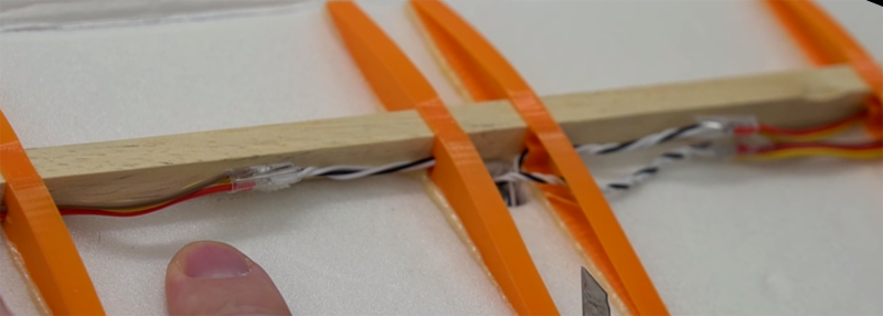
For this build, [Tom] is relying on the old standby, a square piece of balsa. The ribs, though, are 3D printed. They’re basically a single-wall vase in the shape of a wing rib, and are attached to the covering (foam board) with Gorilla glue.
Did the 3D printed ribs work? Yes, of course, you can strap a motor to a toaster and get it to fly. What’s interesting here is how good the resulting wing looked. It’s not quite up to the quality of fancy fiberglass wings, but it’s on par with any other foam board construction.
The takeaway, though, is how much lighter this construction was when compared to the completely 3D printed plane. With similar electronics, the plane with the 3D printed ribs weighed in at 312 grams. The completely 3D printed plane was a hefty 468 grams. That’s a lot of weight saved, and that translates into more flying time.
You can check out the build video below.


This is awesome, love the idea, finally a good use for my 3D printer. Also would like a blog post with more pics, can’t watch Youtube at work…
I still think that if I were to make them, I’d more quickly take a piece of 2×4 and hand-plane the rib shape on it, and then saw the ribs off.
You may end up with the grain going the wrong way, and very weak ribs with that strategy.
What do you mean, may? Of course I would orient the grain lengthwise.
The art of woodworking is in choosing your stock. You then split the wood along the grain and plane it flat along that direction to get nice controlled boards.
I love seeing other worktime hackaday readers.
Best place for a 3D printer in R/C models is linkages, servo trays, mounts, actuators, spoiler assemblies, flaps, hinges, perhaps custom fuel tanks, pontoons for on the water, spinner for the prop, maybe even make a ducted fan!. For ribs and various other typically flat items, you want to cut these from balsa and lite ply with a laser cutter. Plastic is gonna add weight with no benefit to flight.
Balsa ribs are pretty easy to make by hand. Rough cut out of balsa and pin them together in a stack, sand them all together at one time for uniform shape, drill any holes for pushrods, unpin and individually start gluing to your spar. Use a perfectly flat building surface to avoid wing warp. Interior doors are the ONE totally flat item you can purchase easily at the building supply stores for not very much, and they stay flat.
Kit manufacturers that laser cut the flat balsa parts liberally advertise that they are laser cut guaranteeing uniformity, precision, and lightweight work, whereas with die-cut parts you have to sand by hand before building to get them all precisely the same shape. Laser cutting is what we all want for balsa parts.
The 3d printer? Zero doubt would be used for all manner of the control linkages.
Carbon fiber strips on the balsa spar? One lone carbon fiber strip on one vertical side for the whole length makes it incredibly strong. Leading edge is of wing is great place for another strip.
Foam core wings are pretty easy to cut. You can find instructions for the “foam cutting bow and power supply” many places online, cost $30 if you build your own.
With flying models there is one thing to remember. F=MA. Twice the weight is 4X the damage on … err… “landing”.
I would love to see a wing like this but then fabric or tissue coated. It’d be light as anything, especially if carbon fiber spar was used. Carbon fiber is ridiculously strong.
The ribs have a pretty simple shape. You can cut them from foam, couldn’t you?
Thr whole trick with foamboard (esp. the one with paper or cardboard on both sides) is that it is self-supporting and doen’t need neither ribs nor spars. Ok, sometimes you fold some foamboard to make a spar.
My thoughts exactly… if you’re going through the trouble of making a full skeleton wing, just monokote the damned thing.
Ribs?
Without Barbecue sauce?
Hmm, What of ribs of ninjaflex?
I’ve suggested this in RC forums, but no one has “flown” with the idea as far as I know: write a user alterable (wing sweep, scale/size, spar shape and size, washout/in, etc.) openSCAD script which produces the ribs for a flying wing. There would be user-specified dimensioned holes in the ribs for commonly available carbon fiber square or cylindrical tubing sizes.
I did something similar, but I went further and printed all the parts that wouldn’t be straight bits of balsa. The idea was to have similar construction to a laser cut kit https://www.thingiverse.com/thing:1544701 It worked well for a first try