
If you want to measure resistance and you know Ohm’s law, it seems like you have an easy answer, right? Feed a known current through the thing you want to measure and read the voltage required. A little math, and that’s it. Or is it? If you are measuring reasonably large resistance and you don’t mind small inaccuracies, sure. But for tiny measurements or highly accurate measurements, you’d be better off using the four-wire method. What’s more is, understanding why you want to use the four-wire method is a great example of using an understanding of electronics to find solutions to problems.
The Usual Suspect
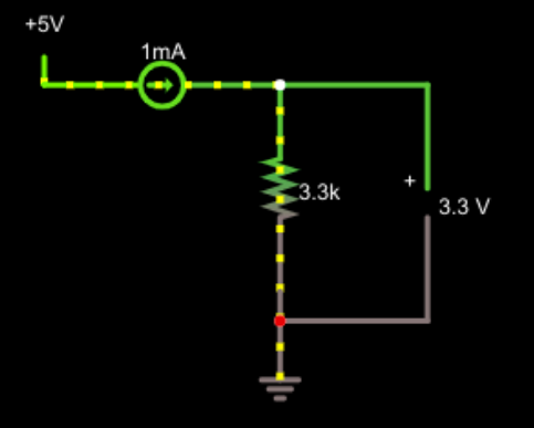 Let’s look at the normal case first.
This is pretty simple. 3.3 / 0.001 = 3,300 and that’s the answer. But real life is a little more complicated. After all, in the simulation everything is perfect, but in reality, wires are not perfect and neither are measuring devices.
Suppose the leads going to the resistor are fairly long. In fact, let’s say they add an ohm of resistance on each leg. So now instead of 3.3 kΩ you have 3.302 kΩ. That’s hardly any difference — about 0.06%. Note that measuring the voltage at the output now gives the correct result for the entire resistance, not just the resistance we are interested in.
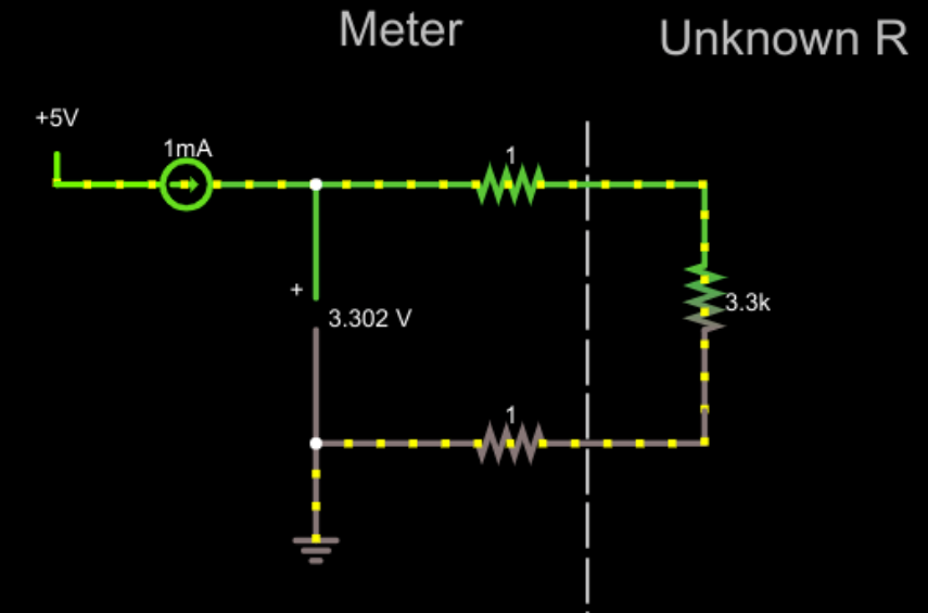
That doesn’t seem like a big deal, right? But it could be. Imagine if the unknown resistor was very small. Even, say, 1 Ω. Now we are off by a large factor! A conventional analog meter makes you zero out the probe resistance by shorting out the probes. But that requires some complexity if you are trying to get the right result to display digitally. In other words, with the perfect setup, you could put a digital panel meter that reads the voltage in the circuit, and read the resistance directly. Zeroing it out would require more effort to get the meter to read zero volts instead of the 0.002 V it would currently read with a short circuit.
Real Life
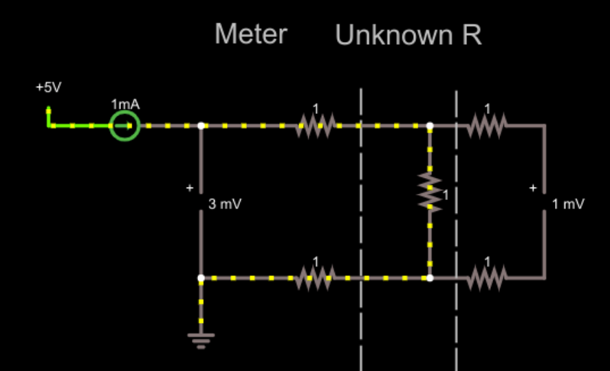 Let’s add a second voltmeter. Since the wires going to the voltmeter are perfect, we’ll also add our 1 Ω resistance to those wires. The voltmeters are perfect, too. In real life they might have a shunt resistance of a megaohm or more. You’ll see in a minute that doesn’t matter very much. But the imperfect wires do have an impact. For now, we’ll live with the perfect voltmeters.
Now the right-hand voltmeter reads correctly, despite the extra resistors. These resistors don’t matter much because the voltmeter is essentially an open circuit. No current flows so, therefore, there’s no voltage drop across the leads. In reality, there’s probably a resistance of 1 megaohm or even more across the voltmeter, but that doesn’t really make any significant difference. The reading drops to .999997 mV. Modern devices probably have at least 10 times that resistance which makes the difference truly negligible.
This is the basis of the four-wire, or Kelvin measurement. Two wires push current through the device under test and two more wires measure the voltage while transporting as little current as possible. The result is a highly accurate resistance reading.
You often hear the current carrying wires referred to as the force wires and the other pair as the sense wires. Typically the sense wires are placed between the two force wires to prevent any additional wire or trace resistance from influencing the measurement. When dealing with small measurements, it isn’t unusual to see the force wires much thicker than the sense wires. After all, the sense wires will carry very little current, but with a 0.01 Ω resistor under test the force wires will have quite a bit of current flowing.
Not just for Resistance
To recap, we wanted to measure a voltage, but were stymied by the voltage drop across the finite resistance of our current-carrying sense wires. Reducing the voltage drop, without resorting to jumper cables, means reducing the current flowing where we’re taking measurements, and the solution is to split into force wires and sense wires. Understanding the relationships intuitively about how changing one thing affects another can help you produce better designs.
This four-wire trick is useful even if you don’t want to measure resistance with precision. For example, high-current or high-accuracy regulated power supplies use the same trick. If your power supply measures voltage at the output terminals, it suffers from the same issues. Sure, you regulate to 5V at the output terminals. But a 1 Ω connector to the load drawing 2A means only 3V gets to the load!
The answer is the same. All regulated power supplies have some version of feedback coming in from the output. A remote sensing power supply will have a pair of small sense wires that connect directly to the load. Just like in the previous case, the sense wires carry very little current so they don’t suffer from as much measurement error. The voltage at the output terminals may be higher than you set the regulator, but the output across the load should be correct.
Many commercial meters — especially the bench type — offer a four-wire measurement option. Now you know how it works and why you’d use it.


Once I was helping my dad fix some kind of electronics project, it was really long ago so I don’t remember what it was exactly. Anyway, he asked me to read the resistance of some component. Me, being young and naive, measured it with just 2 wires. When my dad say me measuring he ran to the garage and when he got back he proceeded to beat me with jumper cables.
Angry you didn’t know how to read resistor color codes?
Reddit is leaking…
At least he didn’t beat you with 4 jumper cables…
So this guy walks into a bar wearing nothing but a pair of jumper cables. The bartender looks at him and says “you can drink here, but don’t try and start anything…”
We use four-wire sensing all over the place at work. Here are some things to consider:
It’s really useful for current measurement if you don’t have the space or overhead for like an INA169. You put down a big current sense resistor (the system I’m working on right now uses 15 milliohms in series with the power input and output) and snake two lines off it. We use 2010 resistors, and layout is important: power comes in from either side into the pads, but the sense lines come out of the inside of the pads towards each other, and are routed as a differential pair to where they’re being measured. Try and keep them single-sided: don’t put a lot of vias in there. Try to keep a ground plane around them and beneath them, and if you have to get near noisy lines (switch node of a power converter, say) route them across those lines at 90 degrees.
Layout packages can make routing force/sense really difficult. If they’re the same net, you have to spend a lot of effort making sure the traces don’t get mooshed together and shorted out somewhere, especially if your layout package allows you to shove traces during routing. They will get shoved together and short and then you lose the whole point of F/S. The best way to do this is net ties, small fake components that physically look like an 0201 resistor (at least the ones I create) but are just a short circuit between the pads. This way your force and sense nets have different names, and don’t overlap during routing. I put the net tie right up against the pad where I need to be sensing. You usually have to build a DRC rule to make the net tie legal, because it looks like a short circuit.
You can get sockets for chips that have force and sense pins, if you need to get accurate voltage sensing right at the pin itself. I’ve never seen these for grid array packaging, but they are available for most packages that have the pins on the outside of the chip package. (They are not cheap.)
Wow. I am stunned. What is next in the list of trivial HaD articles? This could have been written in 1 paragraph and 1 figure. Sigh.
Waiting for your useful contribution to the scene.
Is this technique in any way similar to a wheatstone bridge?
No, but sometimes it was very popular to combine with it. Especially with strain gauges with long cables, you can use 6 cables: 2 for power, 2 for signal and additional 2 to mensure power supply voltage and correct it (you operate on voltage, so long cables make difference).
This is where things get interesting, when Ohms law ‘apparently’ doesn’t work. Of course it’s working just fine, but including the ‘parasitics’ (like Al did in his schematics) is what let’s us know, yes, indeed, Ohms law is still working!
The whole topic though is a proverbial ‘rabbit hole’, neglecting that an actual rabbit’s hole is very straightforward. Pray to yer Gods no serious hard-core old-time instrumentation guys get into this thread, or it will go way deep real fast.
That said, one little aspect here is the meters most hobbyists use are likely not 6 digit traceable, calibrated Agilents or Keithleys. So, with a $10-$20 meter, say 3 digits, traceable to ?, you can’t get too carried away.
I’m thinking the biggest real-world practical application for a DIY/Hacker is likely going to be in current sensing. Assuming your voltage measurement across the sense resistor is to some degree of accuracy, repeatability and precision, one would like to know that the sense resistor (we’re measuring voltage across) is similar in terms of ‘arp’ (accuracy, repeatability and precision). So back to current sensing…..suppose you want to know the actual current being delivered to a motor on an electric vehicle? And here we go! Of course a small resistance value is desirable, that way power is not lost in the sensing resistor. Watts=(I^2)*R. And wow, if the sensing resistor does heat, then you have an additional complicating factor .
So, we are back at the beginning, why are 4 wire measurements important? In a nutshell: to remove parasitics from the measurement. Wire resistances, contact resistances, we dodged ;-) temperature. And places we don’t want to go? Transient currents? Impedance (vs. resistance)? NOooooo. NO. Not there pleeeease. ;-)
SMD tweezer style probes only $5. More for 4 wire
If this circuit and battery would fit in handle, viable product for under $20. Meter leads simpler because the low current PSU is integrated.
Whoops, this comment was for the $1 short circuit test probe article
Many years ago, there was a HAD article that featured a 4-wire ohmmeter from an arduino, OLED display, I2C A/D and a few (precision) resistors. I added a USB charging module and lipo with a power switch and put it in a box measuring a 3-1/2 x 2-1/2 x 1-1/4 inches. Came in at less that $15 (I had the box), not counting the leads.
I’ve used it on countless shorted boards to track down low resistance solder and chip shorts that my IR thermometer couldn’t trace. I doubt it gives exact readings but that’s not needed to find a very low resistance short. I later bought a Fluke bench meter with four wire ohmmeter, but the HAD version is so darned handy!