
In the last Circuit VR we looked at some basic op amp circuits in a simulator, including the non-inverting amplifier. Sometimes you want an amplifier that inverts the signal. That is a 5V input results in a -5V output (or -10V if the amplifier has a gain of 2). This corresponds to a 180 degree phase shift which can be useful in amplifiers, filters, and other circuits. Let’s take a look at an example circuit simulated with falstad.
Remember the Rules
Last time I mentioned two made up rules that are good shortcuts for analyzing op amp circuits:
- The inputs of the op amp don’t connect to anything internally.
- The output mysteriously will do what it can to make the inputs equal, as far as it is physically possible.
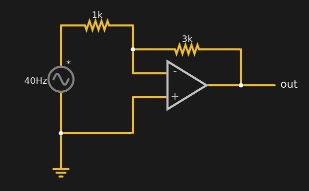 As a corollary to the second rule, you can easily analyze the circuit shown here by thinking of the negative (inverting) terminal as a virtual ground. It isn’t connected to ground, yet in a properly configured op amp circuit it might as well be at ground potential. Why? Because the + terminal is grounded and rule #2 says the op amp will change conditions to make sure the two terminals are the same. Since it can’t influence the + terminal, it will drive the voltage through the resistor network to ensure the – terminal is at 0V.
This virtual ground idea makes the analysis of the circuit simple. You can see on the simulation that the amplifier has a gain of 3. So pretend the input is 5V DC or, if you like, change the voltage source. Since the – terminal is virtual ground, we know the current through the 1K resistor must be (5-0)/1000 = 5mA. Rule #1 says the input terminals aren’t going to look like they are connected to anything, so that means the current through the 3K resistor must also be 5mA and one end of it is virtually grounded.
So what’s the output voltage? (V-0)/3000=.005. If you do a little high school algebra, you can rewrite that as V=.005(3000) = 15V. In real life, you wouldn’t want the output so close to the supply rail, but you get the idea. In the simulator, we only specify the maximum and minimum output voltages for this op amp model, so perhaps the power supply is really +/- 16V. That’s my story and I’m sticking to it.
Gains
For the non-inverting amplifier the gain was equal to the reciprocal of the feedback network’s voltage divider ratio. That is, with a 1K and 3K resistor, the divider ratio is 1000/(1000+3000)=1/4, so the gain is 4. That makes sense, because in that case, we reduce the op amp’s output voltage while it is trying to make the two terminals equal.
For an inverting amplifier, the gain is the simple ratio of the two resistors, since what sets the gain is the equal current flowing through both resistors. If the two resistors were equal, a non-inverting amplifier has a gain of 2, while an inverting amplifier has a gain of 1. If you recall, to get a unity gain in the non-inverting circuit, you don’t need any resistors, just a zero ohm resistor (a wire) between the output and the – input.
What’s the Difference?
Of course, the idea of a virtual ground is really nothing more than restating rule #2. If both terminals have inputs, you have a differential amplifier. These are important for several reasons. One of the biggest use of differential amplifiers is to reduce common mode noise.
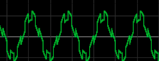 Suppose you have a temperature sensor that puts out a tone from 250 to 300 Hz depending on the reading. The wires going to the sensor are long and you find that you are picking up 60 Hz hum from the AC wiring. Your input signal might look something like the one on the right. The 60 Hz hum is about 5 times a strong as the square wave data signal. How can you recover it?
There are several answers, of course. But if you observe that both the positive and ground wire going to the sensor will pick up the hum, a good answer is to subtract the return leg from the positive leg. Since the noise is the same on both wires, it should subtract out, leaving only the signal of interest. Here’s an example circuit for removing 60 Hz hum:
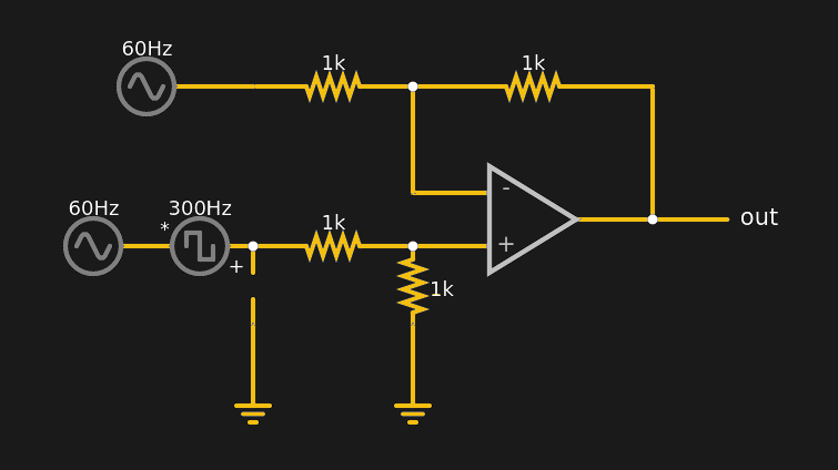
Here, the + terminal will be at 50% of the input signal. That means, by rule #2, that the – terminal will also be at that same voltage. Suppose there is a steady 2V on both inputs. The + terminal will then have 1V on it. That means the – terminal will also have 1V. If the input is 1V and the – terminal is 1V, the output must be at 0V since the feedback network will be like a voltage divider. No matter how the voltages change together, the output will remain zero.
But what happens if both inputs are at 2V and suddenly the input at the + side jumps by itself to 4V? Now the + terminal is at 2V, and this causes the current flowing to change (to zero, in this case). That means the output voltage has to change to set the same current in the feedback resistor. Since that’s zero in this case, the output must also be 2V.
If the zero current is confusing, try a different voltage like 3V in this circuit. When you flip the switch to feed 3V into the circuit, the + terminal because 1.5V so you have 0.5V across the input resistor, which means you’ll need the same current through the feedback resistor and the output will be 1V.
Is That All?
There are a lot more things you can do with op amps, but those will have to wait for a future Circuit VR. While modern op amps are great, they still aren’t perfect. The inputs will have a little leakage. The outputs will not get right up the rail if you draw much current from them in a general-purpose op amp. If you are dealing with high frequency, you’ll need to carefully select parts. Precision circuits may need care for offset trimming and other special design considerations. However, compared to building precision amplifiers from bare transistors, having high-quality op amps is a real time saver.
There are many specialty op amps. Some operate on current inputs. Some have special output stages. For example, comparators are op amps with high speed output stages that tend to saturate quickly one way or the other. There are many choices depending on what’s important to your design. If you want some extracurricular reading on op amp architecture selection, Analog Devices AN-360 is a good overview of the subject.


I continue to dislike the magic “opamp rules” – there’s a much simpler explanation that makes more sense to most people I’ve tutored and can explain more real-world opamp behaviors –
1. If the voltage at the + pin is higher than the voltage at the – pin, the output voltage goes up (and vice versa).
2. The output voltage goes up and down very fast, but not infinitely fast.
#2, spoilsport I was all set to make a wifi RF amp with a 741 :-D
More accurately:
1) when + is greater than the – input, the output is connected to the positive source of the op-amp. When – is greater than the + input, the output is connected to the negative source of the op-amp.
2) when there is very little difference between the two inputs, the output becomes the positive input minus the negative input multiplied by a very large number, as long as this result is within the positive and negative source voltages.
Or simplified: “The output voltage is the positive input voltage minus the negative input voltage, multiplied by a very large number, and capped by the positive and negative voltage sources given to the op-amp.”
This explains all of the basic behavior.
Here again the abstraction to “simplify” things causes confusion to beginners.
The idea that the op-amp produces negative voltages is introducing a silent assumption: that there is a negative voltage source which is never displayed in the circuit. Since this isn’t actually shown in the circuit, and this is what I’ve actually found people to ask, people think that the op-amp acts as a charge pump and produces the negative voltage internally out of the positive supply. The people who didn’t ask that question made the error of connecting the circuit with positive voltage only, and then asking why it doesn’t work.
When you’re only being introduced to these topics, it pays to remain accurate rather than easy.
And again:
>The output mysteriously will do what it can to make the inputs equal, as far as it is physically possible.
This rule makes you think that the op-amp will mysteriously internally inverting if it is connected with positive feedback, and in fact it’s suggesting that positive feedback is not even possible because of the same magic that prevents the two outputs from going different ways.
…two inputs going different ways, rather.
Yes, these “introduction courses” to op amps are a bit lackluster.
I know of a lot of people that think Op amps are magic, but can’t figure out how to make things involving them actually work.
Mostly due to many misconceptions of how they work.
Op amps are very simple devices, so explaining how they operate isn’t hard.
In short:
If the difference between the inputs is positive, the op amp increases its output voltage.
If the difference between the inputs is negative, the op amp decreases its output voltage.
Although, an op amp with an internal charge pump for a negative rail would be fairly handy to have at times. Even if it could only source 1-2 mA.
Apparently there is op amps with integrated charge pumps for generating the negative rail.
The MAX44267 for an example works from 4.5 to 15 volts and generates a negative supply with a similar voltage. Not to mention that this can sink some 17 mA, fairly decent to be fair. Though, wonder if it can do that on both its outputs at once, or if it is total current. But its gain bandwidth product of 5 MHz leaves a lot to be desired.
The ADA4858-3 is a bit more modest when it comes to voltage, only going up to 5.5 volts, but on the other hand capable of sinking some 50mA into its negative rail. But its gain bandwidth product of 600 MHz makes it more interesting as well as the fact that it has 3 op amps in the same package.
There is certainly more op amps on the market with integrated charge pumps, this is just what I found on a quick search, the thought have been gnawing on my mind and that itch needed scratching.
And obviously, the fact that these have a charge pump switching internally does make them a little bit “noisy”. Sadly one has to supply one’s own capacitor for the charge pumps, a minor issue to be fair.
Nowadays fully differential amplifiers (like THS4521) are quite cheap and provide a nice alternative for virtual earth. Keeping the circuit differential really cuts down any noise, though it does sometimes require more passive components.
“The output mysteriously will do what it can to make the inputs equal, as far as it is physically possible.”
Is a statement that I personally have found to be really unhelpful for beginners.
The Op amp doesn’t mysteriously produce an output that makes the inputs equal each other.
The output of the Op amp simply amplifies the difference between the inputs.
Or more correctly:
If the difference is positive, the op amp increases its output voltage.
If the difference is negative, the op amp decreases its output voltage.
And since it is slew rate limited and working within an analog circuit, one can make it have negative feedback to itself, something that makes it have very stable operation.
But put it into positive feedback and suddenly Op amps are a can of worms where the quoted statement is frankly abhorrent advice.
Truly a harrowing cacophony of advices. I recommend that anyone REALLY interested, go to one of the greatest sources for op amp into (if not THE greatest), namely “The IC Op-amp Cookbook” by Walter Jung (1974). There may be some free PDF copies of older versions out there, but it you have to buy one, you should buy one, it’s THAT good. It will not only clear up the mess presented above in short order, but it will continue to show you how to use them in numerous practical circuits. Of course, it references older op amp devices, but its easy enough to extrapolate to newer parts, which in so many ways are much better then many of the older parts.
There are many pitfalls for the unprepared. Did you know that not all op amps can do rail-to-rail on inputs? Or that some will unexpected invert their outputs when their maximum differential voltage input ranges are exceeded? Or that many bipolar op amps do not like their inputs going to the negative rail? And that most older op amps are designed to operate with bipolar supplies and that “ground” is then not the most negative supply rail (e.g. like for 0-5V unipolar supply circuits).
So, the inputs are not “plus”/”positive” or “negative” — they are noninverting and inverting inputs. The statement above: “The output mysteriously will do what it can to make the inputs equal, as far as it is physically possible” is beyond wrong. That doesn’t happen. The op amp has some intrinsic gain and that gain can be used to try to drive the output based on the voltage difference between noninverting and inverting inputs, BUT ONLY IF THERE IS SOME KIND OF FEEDBACK. Generally, only negative feedback (which is not “minus”) if when the output or some portion thereof, is connected to the inverting input. It’s truly what makes the (op amp) world go round. When there is no “feedback”, then that circuit becomes essentially a differential amplifier or in other parlance, a comparator (although comparators are a different enough beast to warrant special treatment. The Jung book has so many great examples (some that need a bit of updating), but it has a boat load of GREAT circuit examples, which is what helped me learn way better than any of my college textbooks, which are often too dry and banal for my liking.
If you REALLY WANT TO KNOW, the get this of any number of other books, but most of my first-hand knowledge was derived from the Jung book, which was brand-spanking new when I was in college (I retired just over 5 years ago). Knowledge doesn’t age, parts do. But never be afraid to go deeper into a subject. Sure, you may stumble at first, but you get up and try again, and again, and again… until you lick that problem.
Thanks, I check into that book.
You mean like this one?
B^)
https://www.amazon.com/op-amp-cookbook-Walter-Jung-1974-05-03/dp/B01FGQ4LLQ/ref=sr_1_2?dchild=1&keywords=The+IC+Op-amp+Cookbook&qid=1610758352&sr=8-2
At $987 I’ll pass on that one.
31 used for $15
I was taught the virtual short/virtual open method. Used to simplify the circuit for analysis and more useful in the pre SPICE days.
One neat thing I’ve started doing is using hex inverters in place of opamps in some contexts. Just needs a feedback resistor, and you get 6 in a package for a very very low price (0.50 in single unit price).
That’s what witches use for self-defense.
Half baked on the back burner at the moment is a back of envelope idea for a flash AD convertor in “logic”
I got opamps teached as if there is a nullator on the input, that wants current and voltage over the input to be null or 0. On the output a norrator that does everything to keep the nullator happy.
“The output mysteriously will do what it can to make the inputs equal, as far as it is physically possible.”
This is not correct by any stretch of the imagination other than when negative feedback is used; in which case it is the negative feedback that keeps the inputs at similar voltages.
For an open loop op-amp or for positive feedback then the op-amp cannot “make the inputs equal”. In these tow cases the gain is that high that the output of the op amp will tend to clamp at the maximum positive or negative value possible.
Most op amps are used with negative feedback and so the inputs will tend to be very close but the op amp doesn’t have a mystical ability to keep them identical.
Negative feedback is used on op amps to create non-inverting amplifiers with different gain settings. The “classic” non-inverting unity gain configuration uses 100% negative feedback by tying the output directly back into the inverting input. Intentional positive feedback is used to create oscillators, generally through a phase shift network that “tunes” the oscillation.
This article, like many textbooks, leaves out mention of the necessity to provide a bias voltage an op amp, just as one must do for a transistor, when using a single supply. This is not optional, and for some reason is rarely mentioned.