Breathing LEDs are an attractive adornment on many electronic devices. These days they’re typically controlled by software but of course there were fading effects back in the days of analog too. [Pepijn de Vos] mixes a little of the new and the old by building a hardware-based fader from a Verilog design and even too the time to explain the process in depth.
Rather than using a microcontroller and software, [Pepijn] wrote the logic required to make the LED “breathe” in the hardware description language, Verilog. You may be familiar with this for FPGAs, but using it to plan out a build with logic chips is just as apt a use. The Verilog was synthesized into a circuit using 74-series logic chips, with the help of work by [Dan Ravensloft] who has made a library for the Yosys Open Synthesis Suite. With the addition of a basic clock circuit, the LED is made to breathe and the rate can be controlled by changing the clock speed.
It’s a fun way to experiment with both Verilog and old-school logic, albeit one that may not scale well. An interesting side note from the Twitter thread, [Dan] estimates that with current settings the PicoRV32 CPU would require over 2000 chips to build. Regardless, it’s an interesting tool and one that likely has further scope for experimentation.
First patented by Apple way back in 2002, the breathing LED has been a popular project for those learning electronics. We’ve even seen it on motorbikes. Video after the break.
[Thanks to Morris for the tip!]


You know. I’ll bet I can make and LED “breathe” using a 555.
Probably easier with a 556. One half to do pwm the other to do the slow fade to control the pwm duty cycle.
Pretty sure it will take more than a single 555 to form multiple digital logic gates, or at least ‘multiple enough’
Of course once you toss the goal away, even a 555 is overkill, as 3 npn’s and a handful of passives will do the trick
Two capacitors and two inductors.
Make a high frequency LC oscillator that sits inside another lower frequency LC oscillator. Sum the two output voltages and feed it to a diode, maybe with a limiting resistor and perhaps something like a neon lamp to act like a spark gap and recharge it periodically.
When I see that on here I’ll make sure to ask why you didn’t just use an arduino ;)
A single 555 can do it, if the 555 is driving an LC resonator with a really long ring out time. But it would have to be matched with the 555 freqency, either by manually changing the component values or perhaps by way of discharging of a capacitor that triggers circuit that extends the capacitance or inductance of the LC resonato, else the pwm would end up slower than the breathing. If you want it to breath and be fully adjustable then two 555s or a 556 would be much easier.
The capacitor voltage will vary from ⅓VCC to ⅔VCC in a triangle-wave like pattern… A little bit of gain and there’s your breathing LED.
Challenge Accepted???
The hardware above seems like a large number of gates for what it does. Perhaps the logic wasn’t minimized before conversion? I can’t tell as there is no schematic and I read VHDL rather than Verilog.
It’s in interesting challenge to make a gate based circuit to vary the intensity of a led, at say 256 levels up and then down once a second starting from say a 32.768 kHz clock.
My first thoughts would be to try using Bit Angle Modulation (BAM) as it’s easier (lower gate count) to implement in hardware than PWM.
Also Xilinx ISE (and assumedly Vivado) will synthesize both RTL and Technology Schematics. I expect Altera Quartus will do the same. These will give minimum gate count implementations of your VHDL or Verilog.
I once made a driver to drive the head stepper of an old dead hard drive for display purposes. The head would move across the rotating platter in a seemingly random motion to simulate how it looks in operation in a PC. It was made with 74xx series logic as that was easier in those days (all hard drives have been voice coil for a long time now) as micro-controllers were not as easy to use back then.
It was a complex things with digital comparators, up/down counters etc. The seek track generator was a counter with outputs like D0,D7,D1,D6,D2,D5,D3,D4 with some inverted to give a random like appearance.
In hindsight I could have it a whole lot simpler with just a carefully designed 8 bit Linear Feedback Shift Register (LFSR): 8 bits for the track permutations (256 tracks), 1 bit for seek direction and 2 bits for the quadrature stepper driver and some dividers along the way.
What do you think about 2 oscillators at slightly different frequencies? XORing them together will make a sawtooth PWM signal.
That sounds like a viable approach.
As the frequencies are close you would need a long counter chain but that may still be less logic than other approaches.
The most significant bit could be XORed with the output to convert from saw tooth wave to triangle wave.
My idea about Bit Angle Modulation wasn’t as good as I thought.
BAM has a time domain resolution of 1/255 or on less than counter binary of 1/256
Beautiful and clever. Thank-you for sharing.
You’ve missed the OMG moment in this post… there is now a 74xx series fitter for an RTL toolchain! Something I’ve been wanting to do for a very long time. With some effort in optimization (for chip count, PCB area, or propagation), this could be huge! Especially if it can eventually output KiCAD schematics rather than netlists.
Indeed that is exciting… I remember a time of similar interest, but now I can’t recall what projects I had in mind where that’d be useful.
One thought, maybe, is if the fuses on a PAL could be read, then converted to TTL, some former ‘black-boxes’ in the vintage-computing realm could be more easily reproducible/modifiable… plop a TTL-equiv circuit in an old PAL’s socket, and open-up access to previously-internal signals. But fuses->HDL is another step, as well. And, fuses may not be readable :/
What’s an RTL-toolchain? HDL?
…I know that I had a crack at trying to make a row of LEDs fade in and out mounted on our server rack pointing inwards, in 1999 — (three years before Apple patented it as per above). Distinctively remember getting our new P3 NT4 server in mid July 99 for our new Scada system and wanted to make the rack really flash to my then boss.
I couldn’t work out the electronics to do it though….
One of the authors here, somehow the article manages to miss both the source code and my article:
https://github.com/ZirconiumX/74xx-liberty
http://pepijndevos.nl/2019/07/18/vhdl-to-pcb.html
The current version synthesizes the a Risc-V CPU in about 800 chips, down from 2000 in the first attempts.
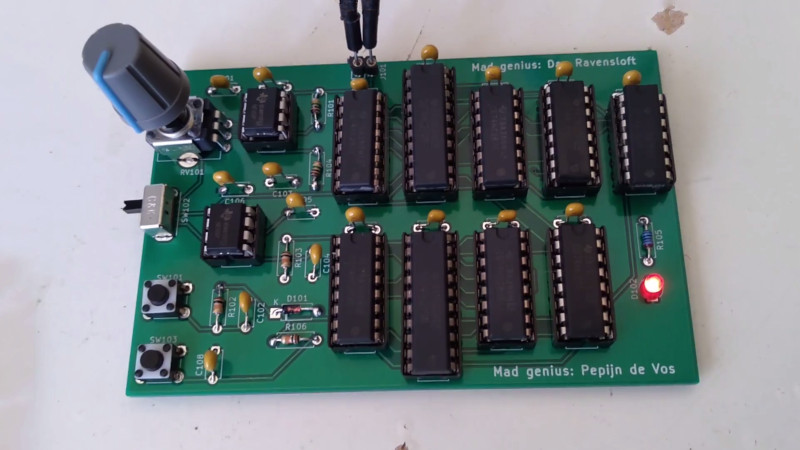
This PCB was kind of a proof of concept that the KiCad generator I wrote works.
A complete CPU might follow later.
I’d really love to see the schematic (PDF or image) or the VHDL.
Without either of these, it just looks like a bunch of 74xx chips to me.