[Mark Omo] sends in his write up on the design of what should hopefully be a sub-$100 oscilloscope in a probe.
Many problems in engineering can be solved simply by throwing money at the them. It’s really when you start to apply constraints that the real innovation happens. The Probe-Scope Team’s vision is of a USB oscilloscope with 60MHz bandwidth and 25Msps. The cool twist is that by adding another probe to a free USB port on your computer you’re essentially adding a channel. By the time you get to four you’re at the same price as a normal oscilloscope but with an arguably more flexible set-up.
The project is also open source. When compared to popular oscilloscopes such as a Rigol it has pretty comparable performance considering how many components each channel on a discount scope usually share due to clever switching circuitry.
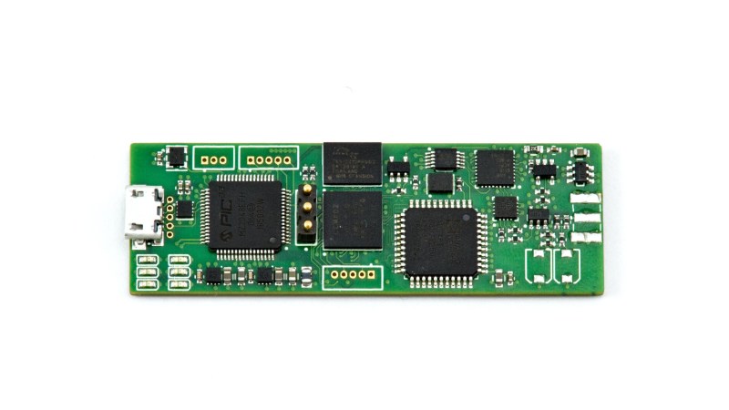
The probe is based around an Analog Devices ADC whose data is handled by a tag team of a Lattice FPGA and a 32bit PIC micro controller. You can see all the code and design files on their github. Their write-up contains a very thorough explanation of the circuitry. We hope they keep the project momentum going!


First question I had is, “How do you get 60 MHz of bandwidth from 25 MSps?”. Then I clicked the HaD.io page and it’s 250 MSps. gg
Second question, “How do you synchronize and correlate multiple channels?” when each channel is coming in from a non-synchronized set of devices each with it’s own LO and unique propagation delays?
maybe a physical sync line across multiple modules? or the pc sends a clock/time stamp?
One of the pictures shows a stack of these with an interlinking bus.
Actually you can get higher bandwidth than sampling rates. That;’s how the modern sampling scope works in non-real time mode. Might want to read up on the specs of scopes.
They assume that the waveform is repetitive and try to construct it with fancy math over a few samples that have different sampling time offsets.
that’s nice! I had no idea consumer hardware could go sub-Nyquist
This is interesting:) The multi sampling with offset. But how they detect the start and end of a periodic signal? What if the signal is crossing zero multiple time with in a single time period?
You don’t use an intermittent signal.
Usually for those things you’re not debugging damaged hardware.
It’s your own PCB/circuit and trying to fix cross-talk, impedance, reflection, drop, jitter, and other issues during design, it’s pre-production.
You just hook probes and inject a (hopefully) constant frequency & amplitude signal rather than meaningful data and look at the distortion caused to a pure square or sine wave.
This way the scope has no issue synchronizing and sampling at (signal_period * N + X_offset) timestamps.
It’s just to check PHY signal integrity, not data errors.
For data errors once you know the PCB traces are good you just capture data past the physical receiver/decoder chip in binary form with some custom software on the receiver’s controller or hook up your favorite FPGA dev board, dump that to a file and write a tiny program to make sense of it.
And even when it’s to check the signal while sending actual data a PLL allows locking onto the overall frequency, at those rates the data is encoded in a way to always have transitions every N bits such as 8/10 encoding. And you force your system to spam data with a factory-test firmware.
You get an “eye diagram” which shows both straight lines (two same bits in a row) and transitions all overlapping so you can visualize signal integrity.
But still not to check if the data sent is the proper payload data.
Uhh, as far as I’m aware you don’t introduce an offset to the sampling clock, as it’s pretty much impossible to do (as in – it takes a couple (dozen) sampling clock cycles for ‘flash’ ADCs to start returning meaningful data), but instead you sample continuously and measure the trigger pulse position with respect to the sampling clock. Because the sampled signal and sampling clock are uncorrelated you essentially sample at random points in the signal. After a couple (dozen? hundred?) of such sample packs you can reconstruct the original signal at a much higher effective sample rate. (“Random Interleaved Sampling” is one of the many names for this technique).
That is not to say you can’t have a number of interleaved ADCs do the sample-with-an-offset thing, but it’s real-time and a different thing. I remember hearing somewhere the venerable DS1052E did this with 10x discrete 100MSPS ADCs, but don’t quote me on that. Doing it on the die level is pretty much how Keysight and the others get their ultra high real-time sample rates (search for interleaved ADCs if you’re interested).
Sorry for the necroresponding, but I’m working on something similar and thought I’d leave this info here for anyone browsing this comment section in the future
Also old vacuum tube scopes used the equivalent time technique to observe fast repetitive signal. E.g. the Tektronix 500 series Tek scope with a 1S1 (sampling) plug in was able to show repetitive signals in the GHz realm already in 1965, more than 50 years ago.
Easy-peasy. The USB host broadcasts the tokens every 1ms, microframes every 125us, and every token has a 11-bit counter value. If you’re careful, you can sync PLLs down to 10ns jitter that way.
The problem with these projects is never the hardware. How many fully open source scopes do we have already? A lot.
How many are actually supported by a great and usable front end software? Not many.
This is also starting to be the difference between a good oscilloscope and a bad one. Both have the same specs, maybe even the same hardware (ADCs, amps, memory, etc) but one runs a crappy useless unusable buggy software while the other one runs something that is refined over multiple years, maybe even tens of years.
Yeah, how this goes into a case is an afterthought….
Maybe you should start a modern opensource oscilloscope project. Probably an idea to reach out to some of the gnuradio people as well because I’m sure that they would have a lot of ideas when It comes to handling a diverse range devices, with many configuration options, providing raw data to process
A few years ago I wrote a driver for Sigrok to drive a DSO, but there still is no Sigrok frontend that allows it to be used comfortably.
Note this is an issue even with brutally expensive ‘scopes. We have constant arguments between the Tek people who just loathe LeCroy’s hardware/software interface (“How do I do cursors? I hate these things!”) and vice versa, and we all hate the Yokogawa scope’s interface, and I won’t drop names because we’re still not sure exactly what’s going on but one of our $40,000 scopes has a trigger mode that when it gets a trigger it freezes and we have to reboot the scope.
Good scope interface design seems to be much harder than I would have thought, and it’s convinced me that there’s not really any such thing as universally intuitive interface design.
Hah yes, that’s so true, it’s really polarizing. I can’t wrap my brain around LeCroy interfaces even if my life depended on them. Keysight/Agilent/HP and Rohde, though, comes very easy to me.
Haha.. been there, done that.
A lab where I used to work purchased a ‘showroom model’ LeCroy 40GHz scope for nearly 90k euro. That’s too much money for a 2.5kW space heater that runs windows. I’ll second the marginally useless interface. It sat basically unused for over a year because it was such a waste of time.
What’s wrong with yokogawa, I spent much time on a nice 4 channel one in grad school and never had any issues? Never used a lecroy, but plenty of experience with tek + agilent (or whatever they are calling themselves today lol).
Like the general idea, but not fond with choice of processor and ADC. Perhaps someone could explain these design choices.
An external voltage divider to provide the 300V input range? What does this do to the system noise level? I suppose that the 8 bit resolution makes this less of an issue in terms of percentage of full scale.
Also, you might want to look at IEC61010-1.
Awesome project! I noticed that 5V USB goes directly to 5V analog with only a single inductor in between. USB will generate a lot of noise on the sensitive analog frontend. Also the -5V is generated by a switched capacitor voltage converter that also generates a lot of noise. Have you considered using filtering and/or using LDO’s that reduce the analog supply voltage to +/-4.5V for example? Also be aware that USB voltage can vary between 4.75V and 5.25V.
Just convince the gamers that to truly experience their games as the authors intended they need soundcards that can go up to 100MHz. Then the market will bring down the price by mass producing our “oscilloscopes”.
Neat project. Interesting tangent is the design reminds me of the spectrum analyzer project I want to work on that basically turns an oscilloscope into a spectrum analyzer without using a computer and interface.
I’m thinking designing to work with the 500MHz or 1GHz Tektronics scopes I have.
Now this design has me thinking from an inspiration perspective along with the attenuator/limiter project inspiration (https://hackaday.com/2019/12/15/a-modern-take-on-a-piece-of-old-test-equipment/ …note that the comments appear to be disabled or hacked out) to try to design into the size of a probe like attachment where the older versions of the oscilloscope to spectrum analyzers adapter were larger desktop size devices. https://www.facebook.com/groups/electronicdesign/search/?query=spectrum%20analyzer&epa=SEARCH_BOX
Neat to see the scope and other analyzers becoming so compact.