Easy access to reliable electrical power is something a lot of us take for granted, but in developing countries or after natural disaster, it can be a rare commodity. [Daniel Connelly] has been working hard to develop infrastructure people can build themselves, and his latest project is a 200 W water turbine (video after the break) that can be built for about $50.
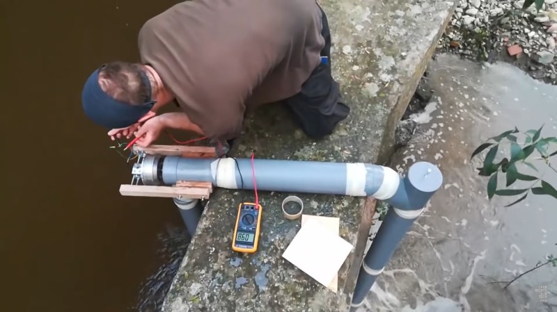
The core of the system is a wheel and motor from a hoverboard. What looks like 110 mm PVC tubing is connected together in a U-shape that can be mounted over the wall of a man-made channel. The inlet side is shorter than the outlet, and the system must be filled with water to allow the flow to start, like a siphon. The first two versions had the impeller sitting on the end of the outlet tube. V1 used a scrap plastic radial impeller of unknown origin, and did not work at all. V2 had a 3D printed impeller that worked pretty well, but the rotation speed wasn’t high enough to produce the voltage that [Daniel] wanted.
V3 used a large computer fan that was mounted in the short horizontal piece of section of tubing at the top of the system. It worked spectacularly well, producing about 55 V AC over a single phase of the motor, which should hopefully end up producing about 90 V DC and 200-500 W after rectifying the 3-phase motor output. This only however indicative, we would really like to see it tested with different loads connected. The output will also be dependent on the flow rate and head pressure of a particular stream/channel/river, and [Daniel] admits that they had pretty much ideal conditions for their tests. If hoverboard motors are hard to come by, a motorcycle alternator should also work well.
[Daniel] is still working out the kinks of the system, but as with his other designs on OpenSourceLowTech he will release the full open source design and tutorials as soon as he is ready. We are looking forward to seeing the system implemented out in the wild. For off-grid power, home built and 3D printed wind generators are another popular topic around here, if you don’t have a handy channel nearby.


If you get 50v open circuit, doesn’t mean you get 50V under an actual load.. Am I mistaken here?
No, this is not the case. He’s measuring the output with a high impedance load, which isn’t sinking very much current. Think about Ohm’s law. As you put a load in circuit for a max output current(which would’ve been a better thing to show) the current times resistance would give you a specified voltage. The more loads in parallel, especially ones for household comfort, such as compressors and heating elements, the resistance will go down.(resistors in parallel). The lower the resistance, the more current you need to maintain voltage constant. If current can’t be regulated to keep a constant voltage then voltage will droop.
Maximum power drawn when the external load = (equivalent circuit) internal resistance
So at max power delivered to external load, you can expect the voltage at the load to be 1/2 of open circuit voltage.
It depends on what the limiting factor is, it’s not hard to engineer the generator to never reach capacity with the given turbine and penstock.
You don’t want to draw the maximum, because by the same effect the efficiency of the system becomes exactly 50%.
The generator internal impedance should be as small as possible, at least 10 times smaller than the load impedance, which means the voltage under load doesn’t sag that much. The power rating of a generator comes not from its internal resistance, but from its ability to handle the heat. If the generator heats up as much as the power it puts out, it’s not going to live very long because the insulation degrades and develops short circuits.
Of course, if you can cool the generator then you can increase its rating at the expense of efficiency.
With permanent magnet generators, you also have to take into account the fact that neodymium magnets lose their field at a certain temperature, so you can destroy the generator by overheating it. The strongest grades start losing their field at just little over room temperature and become irreversibly demagnetized above 80 C. This depends on a number of variables, including the shape of the magnet and the magnetic circuit it’s in, so a hard definition can’t be given other than “keep your generator cool”.
Displacing water from one side to the other and with another unit displacing it back again, together with a more efficient turbine and generator may be worth doing.
o_O
+1
Maybe we can also add a battery and a charger, and have the charger run off the battery while charging it, so that it never drains
http://trollscience.com/image/f/full/8c6ac6fe0aa5ec1952e8e274f6df0f5e.jpg
Science bitch!
I love it!
Can’t tell if you’re joking
They’re wasting a lot of water.
A standard 110 mm PVC tube like that with 3 meters of water head will flow at 37 liters per second, and produce a potential power output of 1 kW.
200-500 W is terrible efficiency – this is why micro-size hydroelectric dams tend to be built with Pelton turbines. They’re easier to optimize and can reach up to 90% efficiency with as little as 5 liters per second flow. With the same head, they’d be making 200 Watts with just 8 liters per second, so the system could be installed in places where there’s much less water available. After all, you don’t want to drain the reservoir empty.
https://www.youtube.com/watch?v=Jd5BN7SPkqI
Pelton turbine is great
How to build or where to buy Pelton wheel alone ?
Yeah, the poster seems to have missed the fact this is using something you could mock up yourself…
Judging from Luke’s reply below, they are missing the point due to their desire to show off how much they know about the subject.
The basic principle of a pelton turbine is very simple. You just need a wheel with little cups welded around the perimeter that catch the water jet and turn it around 180 degrees.
They sell the cups separately, but I’ve seen people make them out of old spoons. They don’t absolutely need to be specially shaped like that – that’s just an optimized shape copied from larger pelton wheel that use the jet to self-center, because a megawatt-scale turbine would run hard on the bearings.
More precisely, the Pelton turbine is an impact type turbine. You can imagine it as throwing an egg and catching it without breaking it. The jet of water hitting each scoop imparts an impulse on the wheel where the maximum energy transfer happens when the wheel is spinning at half the speed of the jet – so you have to match the generator and load to the wheel, and to the water flow, and you’d ideally need a regulator on the water flow if you want to conserve your water resource. If you don’t regulate the water, then you need a dump load to push the excess power in. Otherwise your turbine speed will fluctuate up and down with the load and the power output goes all over the place.
The shape of the scoop is simply to increase the time it takes for the mass of water to slow down and spread the impulse over time to reduce the amount of backsplash and increase the efficiency. When the scoop is designed exactly right, the water doesn’t spray out – it just falls off the scoops having lost all its kinetic energy.
The usual shape of the scoop has two lobes with a ridge in the middle because the idea is to not have the water spray back against the incoming stream. It could be done with a single bowl, but the incoming stream would have to be off-center to the wheel and cause some forces which would twist the wheel. This is not important with micro scale systems because the forces are not that great, but everyone copies the two-bowl design anyways because it’s relatively easy to do. You can 3D print the scoops and just bolt them on to a flat disc, or weld some spoons together and that’s it. There’s actually not that much optimization that needs to be done unless you want to shave that last percentage point off – but if you’re already happy with 20% efficiency then even the worst Pelton wheel would be a massive improvement.
Is it also a design that meets the found parts and price goals?
You can’t build a proper functional hydroturbine on found parts and $50 either. For example, the computer fan blades are made of brittle plastic that will break out of fatigue in about two hours, or the first time the tube sucks up a small twig.
But the main issue here is the water use, because you need a body of water with enough drop and enough flow. The less water you use, the more places you have to install a microturbine, but it’s going to be a difficult task anyhow because usually such bodies of water are already in use, such as irrigation canals.
Thirdly, I don’t like the “poor people don’t need much” attitude where you’re solving developing world issues by having six households share a 200 Watt turbine. It’s literally a cell phone charger and a LED light for each, and that’s about it… if you really want to provide opportunities and actually help solve poverty, you need much more. Kilowatts more, so the people could run fridges and washing machines and other labor-saving devices.
exactly
solar panels or wind turbine can the same job and be more reliable, generating more power
The water turbine unlike solar or wind can deliver power 24/7 if there is sufficient water supply.
So can a 50 Watt solar panel and a car battery.
Again, the water supply is going to be the biggest issue. You just can’t run a micro-turbine like that without any intake filters because it will be clogged or broken in no time.
There’s a thing called a Coanda screen filter, which uses the flow of water to keep itself clean and remove particles larger than small grains of sand from the water supply. It’s the simplest filter design you can have, but as it’s an overflow filter, again you need more water than just what the turbine takes. Having a turbine and some pieces of sewer piping isn’t helping you at all – you need to build all these other things, lay down concrete boxes for the sumps etc. to actually have a working miniature hydroelectric plant.
https://www.aquashear.com/wp-content/uploads/2017/03/AquasheaTECHNICAL.jpg
This video claims its actually a fairly good choice for the low head and pelton turbines need higher head / pressure:
https://www.youtube.com/watch?v=k0BLOKEZ3KU
The main issue with micro-turbines is water availability. Typically you just don’t have the amount of flow to run a Francis turbine because you’re operating with small streams down a hill, so with what little water you get on average, you’re better off trying to maximize the head height by extending your pipes further down the hill and running a Pelton turbine off of the pressure.
If you have a larger body of water, say a small river with a small drop, then the question of micro-turbines is rather moot because you already have to do significant earth moving to make any use of it, or you build a more traditional water wheel design.
Or as you can see from the graph in the video, in micro-power systems where you’re looking at flow rates on the scale of 1 m^3 per second, the Pelton turbine is really the only viable option. In these micro systems, the flow rates are on the order of 0.01 m^3 per second where the Francis turbine just doesn’t make sense because the flow speed isn’t high enough for it to function right.
If you want to see how a “propeller” type generator would have to be built in order to work at low head and high flow in a micro-scale system, the turbine would have to be designed quite differently. In fact, it has been done:
https://www.youtube.com/watch?v=XjEgFlngZ04
thank you
could you refer me to known to you small hydro power solutions ?
I think the whole point was for cost optimization, rather than efficiency optimization.
What’s the point of cost optimization when the thing doesn’t really work?
There’s rarely a source of water where you can just flop a piece of tube over a concrete barrier and get ten gallons a second water flow – usually those places are built for a reason and the owner of the barrier won’t like you emptying their reservoir.
Elsewhere, you’ll most likely have to lay half a mile of pipe to get a few meters of head, and you need to build a filter box with a sump, a gate, and lay down some foundations for a turbine house and anchor the piping down somehow. Changes in the flow have the same effect on a 110 mm pipe as they do to a garden hose – it moves around.
The turbine isn’t going to be the most expensive part of the operation because you’re looking at spending thousands of dollars for everything else.
I might be wrong, but I don’t believe you will get a good efficiency from a pelton turbine with only 3 meters head.
Pelton are used only in high head water.
For the rest I agree.
Dude! There is no Pelton wheel setup that can generate 500watts with 3meters of head through a 110mm pipe.
Your decieving people when you say 5 litres per second. You failed to mention with huge pressure from 50+ Meters of head. How can you even compare this portable $50 diy setup to that? You can’t! Can i pack that on a backpack and setup in a few minutes like the $50 diy generator? Get off your high horse you’re making a fool of yourself.
And don’t forget the electronics. 90 Volts out of the generator is a little small for transmission unless you live right next to the stream (and you don’t mind the noise). Cable is expensive, so bumping it up to 220 Volts with an inverter would save a bunch, but cost the inverter, and a battery, and a charge controller…
Suppose you try to do it with regular cheap 2.5 mm^2 or 13 AWG cable; at 90 Volts and 500 Watts you’ll need almost 6 amps of current and that loses you about 7-8 Volts and 40 Watts for every 100 meters, but, since the generator can’t maintain 90 Volts under load, you need more current and you lose a lot more. The question becomes, which is cheaper? Using a thicker cable or adding an inverter and just running 220 Volts through it?
Either way, you’ll spend a lot more than $50 on that part as well.
Though of course, if you want to run by the code, you’re limited to 50 or 60 Volts anyways unless you have electrical engineer credentials, so there’s that to consider as well. Check your local law.
Hi, this is the guy in the video. Thanks for the write up.
Couple small corrections and clarifications:
“wheel and motor from a hoverboard” the wheel is the motor, 350W three phase AC permanent magnet.
“What looks like 110 mm PVC” yep, but transitioning to 125mm for the drop, so as to increase the water velocity across the impeller.
“we would really like to see it tested with different loads connected” I’m currently working on more fully testing and optimising the design here in Berlin. Power output data will be broadcast soon.
Water availability has been raised, what’s pictured here isn’t quite the ultimate configuration and use case I have in mind, rather; essentially just a length of tube with impeller and alternator which can be dropped into any waterway with a couple meters drop, likely inclined rather than vertical. So that the water is sucked into the tube, accelerated by gravity, and then ejected into the same waterway with power extracted. No significant earthworks etc would be required.
That test site in Catalonia was particularly ideal, but what I’m aiming to design and broadcast should be more versatile in terms of where you can put it, although also put out some degree less power.
As mentioned, the aim of this is for low cost and accessibility over maximum efficiency, although I am also working on optimising the design as much as I can. Also the fact that it’s essentially portable and easily maintainable will hopefully make it a lot more useful to the tens of millions of people in the world with access to low head waterways.