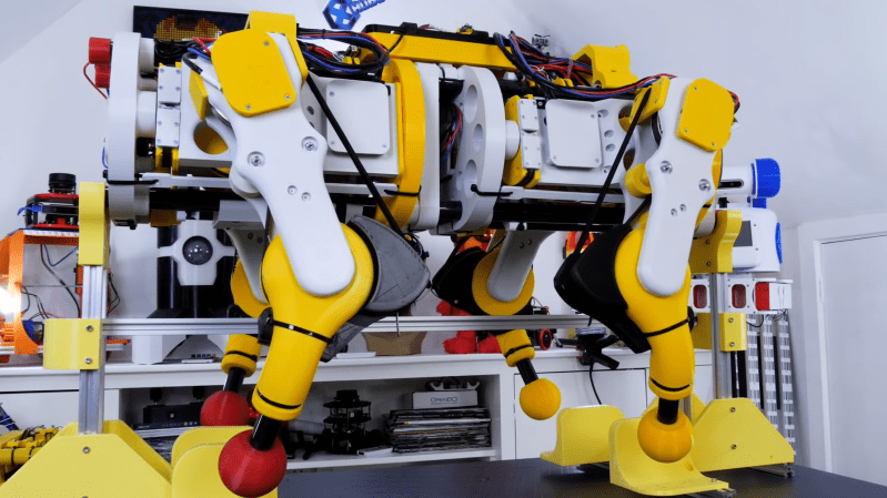
One of the challenges of many walking robot designs is the fact that they draw current just to stay upright. This was exactly the case for one [James Bruton]’s quadruped robots, where the knee motors were getting too hot to touch. Adding springs to take some of the load is not as simple it might seem, so [James] created a bungee assisted cam mechanism to do the job.
For a normal spring-loaded lever, force is proportional to how much the spring is stretched, which will require the actuators to draw more and more current as it lifts the leg higher. For the spring force to remain constant throughout the range of motion, the length of the lever arm must become continuously shorter as the knee is bent. [James] did this by stretching a bungee cord around a cam. The added bulk of the cam does however cause the knees to knock into each other in some scenarios, but [James] plans to adjust the robot’s gait to avoid this. He didn’t get around to actually measuring the current draw reduction, but the motor temperature has dropped significantly, only being slightly warm after a test run.
These tests were done with OpenDog V2, but [James] is already working on the design of V3, which will use 3D printed cycloidal gearboxes. At the moment, that build is still being delayed thanks to the global component shortage.


It looks like a job for calculus of variations. At least for an approximation, because bungees are not conservative like a spring.
Re: Exponential curves and all that, the force for a spring is proportional to the distance stretched or compressed. For constant torque at the joint, science tells us the radius of the cam should increase linearly, which is an Archimedian Spiral (or arithmetic spiral). Or so it would seem.
“Opendog” sounds like unnecessarily cruel animal experiment…
Yes, and not to get too Pavlovian, it does turn the stomach a bit just to hear it.
Well, “Hotdog” isn’t much better ;)
Wow. An openface sandwich must be revolting to you.
No, because I open my face to consume one!
B^)
Adding spring is such a simple Idea it must have been thought off many times before.
But how and where to add them has … room for experimentation.
How about adding the springs between the motors and the mechanical parts. It would make control of the whole thing more complicated, but if it’s combined with a mechanical brake the spring tension can be locked in any position.
With some flywheels on the motors, it’s probably possible to exchange energy between the flywheel and the legs in such a way that a certain gait tan be maintained with minimal energy input, but this also requires complex mechanical stuff such as a “reversible” gearbox.
I did only see a part of the video though. I stopped it at the second advertisement.
It is A solution for particular cases, but not universal to the problem. Some animals like kangaroos use this method to reduce energy consumption, but the issue becomes that you have to fight the spring tension when the limb is not loaded up, and the spring tension has to change with varying masses and direction of force – it only works properly for one particular loading scenario.
The more common solution is passive dynamic walking. Humans have locking knees, which turn our legs into stilts when we’re standing, and pendulums when we’re walking. Same thing for horses, antelopes, etc. animals that spend most of their time standing up or ambulating relatively slowly over long distances. This is generally what we would like from our robots as well – because we’d like them to be pack animals or humanoid workers suited for the same tasks we are. The problem is that the control algorithms are either too slow or too simple to handle seamless transitions between passive and active walking, so the mechanisms are built according to active dynamics and using power to maintain control. It’s brute-forcing it.
Passive dynamic balance represents a “singularity” or a discontinuity to the control algorithm where it suddenly has no way to affect or predict the outcome, so the assumption of continuous mathematics like in PID loops goes out the window entirely. Instead, the algorithm must start observing the environment to predict where it needs to plant a foot to have the desired outcome, but the problem there is that the robot is dumb, deaf and blind – it doesn’t know where it is or what its surroundings are because that’s the harder problem – and people are trying to solve the simpler problem of active dynamic balancing first.
All the designers are trying to come up with clever complicated mechanisms to bypass the mechanical problem first because they don’t have a full or even a partially working solution to the second problem, and because adding more computing power also starts to suck up energy like no tomorrow, because AI is really really inefficient. So they’re stuck at using too much energy one way or another.
https://en.wikipedia.org/wiki/Passive_dynamics
>”Passive dynamic walkers such as the Cornell Efficient Biped[4] have the same specific cost of transport as humans, 0.20. Not incidentally, passive dynamic walkers have human-like gaits. By comparison, Honda’s biped ASIMO, which does not utilize the passive dynamics of its own limbs, has a specific cost of transport of 3.23.”
So basically you have a 16x disadvantage in trying to maintain active balance with power, which is why the bungee cord helps by holding the robot up in the static case, but now every time you lift a limb off the ground, you have to fight against the tension and use more power in actually moving the robot. The slower you move, the more energy you spend because maintaining static torque with an electric motor is very expensive.
I have no idea about mechanics, please don’t beat me. Would you think attaching 2 opposing flywheels and 2 high speed clutches on the dc motors help in anyway? In the startup phase the motor spins up the free flywheels to store mechanical energy and a controller engages the clutches once more torque is needed for movement.
Side question: Can’t a clutch function as break so minimal energy is needed to hold the legs?
Slipping the clutch gets you out of the problem of doing zero-rpm torque with electric motors, but it just swaps the problem for a burning clutch.
But yeah, you can lock the joints down with a clutch to stop using energy when the robot is standing still. Not so much when it’s moving.
“I only watched part of this 15 minute video detailing a year-long development process, but here are several extremely complicated entirely hypothetical ideas off the top of my head about how he could do it better”
Could you use a worm gear reducer to get more gear reduction and irreversibility so the legs won’t bend unless driven by the motor? I used a 30:1 worm drive in my 3D printer’s Z axis and the 3.5 kg bed assembly doesn’t move when power is cut. You can get injection molded nylon worm/disc gear sets for garage door openers pretty cheaply…
You can, but when you drop the robot down it will break the gears.
You should watch the Opendog series – he started with v1 using ball screws to drive the joints, but had problems because they were TOO rigid and had no compliance.
v2 is deliberately a bit “bendier” using back-drivable gearing and limited motor holding torque as a “virtual spring” to allow a bit of flex in the otherwise rigid legs. He’s done a lot of other standalone experiments with compliant mechanisms using elastic members between the motor and armature.
There is an interesting article that said researchers found that even a dead flamingo can stand on one leg, so they can balance using zero energy, maybe he could apply something along these lines to his robot?
https://theconversation.com/scientists-balanced-a-dead-flamingo-on-one-leg-to-unlock-the-birds-standing-secret-78231