Measuring resistance doesn’t seem to be a big deal. Put your meter leads across two wires or terminals and read the value, right? Most of the time that is good enough, but sometimes you need better methods and for those, you need more wires, as [FesZ] explains in his recent video that you can see below.
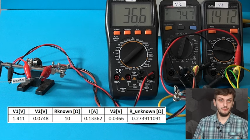
In the usual case, the meter applies a known voltage and measures the current which, by Ohm’s law, gives you the resistance. It is also possible to control the current and measure the voltage — doesn’t matter. [FesZ] shows how many meters measure voltage across a known resistor and the unknown so that a precision voltage or current source isn’t necessary.
But there are a number of problems with this simple method. For one thing, the test leads have resistance as well. So some voltage will drop across them, contributing to measurement error. Sure, that extra 0.5 ohms won’t matter if you are looking at a 100K resistor, but if you are trying to measure, say, the heated bed of a 3D printer, that extra 0.5 ohms is a large percentage of the total measurement.
 Bench meters for lab use often support 4-wire measurements. As [FesZ] shows, this method measures three different voltages to try to negate some of the measurement errors. We liked that he used three different meters to show how it works and the difference between a 2-wire and 4-wire measurement on a small resistor.
There’s an even stranger method using 3 wires to save on wiring for, say, a sensor a long distance away. There are actually at least two ways to use 3 wires, and the video covers both of them.
For measuring resistors in a circuit, though, you need a whopping six wires. This technique uses the two extra wires to control a balance voltage that keeps the current between the unknown resistor and the rest of the circuit at zero. This prevents current flowing except for the measurement current. You’ll see a simulation of how this works in the video.
We’ve looked at 4-wire measurements before if you want some practice simulations to try. Probes for this measurement are a popular project, too.


“For one thing, the test leads have resistance as well.”
Would it make sense to measure resistance across the probes (touch them together) and offset the measurement by that amount? Make it a function when you put the meter in resistance mode to touch the probes together before taking ohms measurements.
Then again, temperature can affect resistance values as well so there is that.
You could, and that would help, but theres also other resistances, like contact resistance, that come into play. Basically, if you’re ok with some inaccuracy, then 2-wire is fine, and if you want high accuracy, you need 4-wire. You can try to improve the accuracy of the 2-wire by compensating for these things, but unless you don’t have the equipment, its much better to just use 4-wire.
So assuming your probe wires are reasonably low resistance, the other factors outweigh the resistance in the wires, so not much value in measuring and subtracting the people wires?
That was common on old analog meters where you would zero before the measurement.
My Fluke 87 has a delta button that zeros out leads for both resistance and capacitance measurments.
My Fluke 8842A has an offset button that works in volt and resistance mode as well.
His videos on PLLs and switch-mode power supplies have been amazingly helpful to me. He manages to explain electrical concepts simply without hiding behind a mask of academic language. Very approachable content. I think HAD’s article on his hot-loop noise video is what introduced me to him.
If the test circuit is more complex with multiple current paths parallel to the resistor, presumably you need more opamps and wires for each parallel path?
What, no measuring it with one wire via rf? :D
This is a really neat article with potential to expose all sorts of ‘4-wire’ situations, as well as a good way to enter a discussion about common mode noise. And sort of on the flip side is a power supply you don’t see very often, the 4-wire power supply with 2 ‘power’ and 2 ‘sensing’ leads. So, if you want to exactly, exactly deliver 12.1234 volts to a load, the sensing leads (connected right at the load) allow the power supply to boost it’s output to compensate for the voltage drop on the ‘power’ leads (which deliver actual current). Turn that around and the parasitics all work to better explain the 4 wire ohm-meter.
Last year, I found another issue with measuring resistance using only the two leads: modern meters test with pulses. My Pokit meter was reading about 500 ohms, and my Greenlee* was reading as an open circuit. The Cold War TS-505 read 155 ohms, which is about what the seller had measured. I was curious, though, so I hooked up a 9v source and read the current: 60 mA. This was the same for all 3 meters.
The only hitch was disconnecting the power supply. I got a significant spark. 2 kV transformer windings have lots of turns.
*I know that Greenlee didn’t actually make the meter, but it’s been reliable for a couple of decades. The frequency counter is also surprisingly sensitive, even if only limited to 4 significant digits.
Oh. For a moment I thought you were saying it was so sensitive it caught your pulse as you touched the leads.
“HOW MANY WIRES DO YOU NEED TO MEASURE A RESISTOR?”
Zero?
Either trust the manufacturer to make the package size in-spec.
Or get out your calipers.