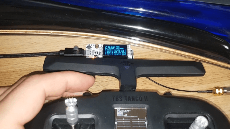
For those building their own remote controlled devices like RC boats and quadcopter drones, having a good transmitter-receiver setup is a significant factor in the eventual usability of their build. Many transmitters are available in the 2.4 GHz band, but some operate at different frequencies, like the 868/915 MHz band. The TBS Crossfire is one such transmitter, and it’s become a popular model thanks to its long-range performance.
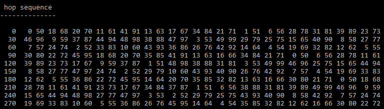
When [g3gg0] bought a Crossfire set for his drone, he discovered that the receiver module consisted of not much more than a PIC32 microcontroller and an SX1272 LoRa modem. This led him to ponder if the RF protocol would be easy to decode. As it turns out, it was not trivial, but not impossible either. First, he built his own SPI sniffer using a CYC1000 FPGA board to reveal the exact register settings that the PIC32 sent to the SX1272. The Crossfire uses channel hopping, and by simply looking at the register settings it was easy to figure out the hopping sequence.
Once that was out of the way, the next step was to figure out what data was flowing through those channels. The data packets appeared to be built up in a straightforward way, but they included an unknown CRC checksum. Luckily, brute-forcing it was not hard; the checksum is most likely used to keep receivers from picking up signals that come from a different transmitter than their own.
[g3gg0]’s blog post goes into intricate detail on both the Crossfire’s protocol as well as the reverse engineering process needed to obtain this information. The eventual conclusion is that while the protocol is efficient and robust, it provides no security against eavesdropping or deliberate interference. Of course, that’s perfectly fine for most RC applications, as long as the user is aware of this fact.
If you’re into decoding RF protocols, you might also want to try using a logic analyzer. But if you merely want to replicate an existing transmitter’s signals, it might be easier to simply spoof a few button presses.


Most impressive :-)
Anyone else note the small magnet, probably used as a cable tidy.
Heck yeah, happy to see this amazingly documented process of reverse engineering finally getting some recognition. The amount of detail provided and the process is really interesting and educational. Also interesting to see that the manufacturer’s claim of “the latency for 12ch vs 8ch is virtually the same, no difference” is only in regards to the first 4 channels, which is a little bit of lying by omission. The things we wouldn’t know if not for curious engineers <3
However the first four channels (mapped to the sticks) are generally the only ones that really benefit from ultra-low latency; everything else tends to get trumped by the amount of time it takes for the operator to reach for the respective controls. It would have been a lot better if they’d been upfront with the details though.
Great job! Would be interesting to see the same with Ghost.
I would be curious about a new study about the encryption they added
Crossfire? Or Ghost?