There’s one component which used to be ubiquitous in every experimenter’s junk box, but nowadays unless you happen to be a radio amateur the chances are you may not have seen one in a long time, if ever. We’re talking of course about the air-dielectric variable capacitor, the tuning element for millions of radio receivers back in the day but now long ago replaced by much flimsier polymer-dielectric parts. There’s still a need for variable capacitors though, in particular a high-voltage variant for use in magnetic loop antennas. It’s something that [Ben] had a need for, which he solved with a clever combination of PCB material and 3D printing.
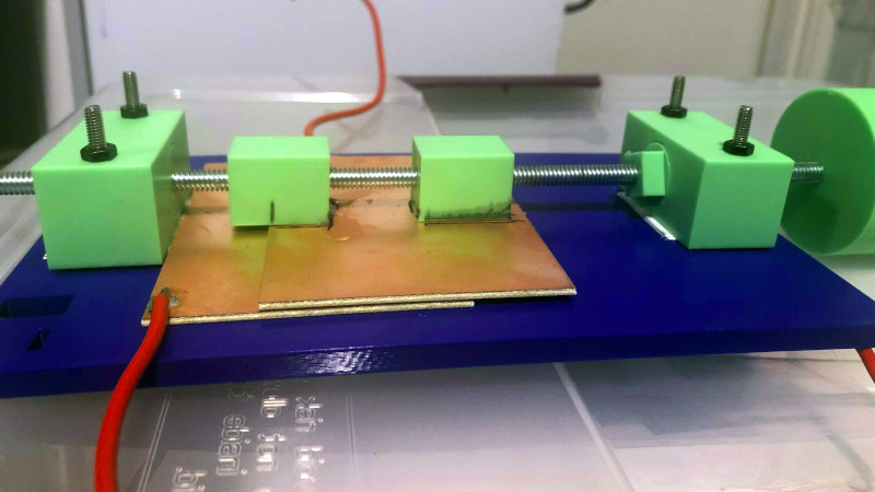
While the variable capacitors of yore invariably used intersecting vanes on a rotor, this one has two large parallel plates that intersect as one is moved over the other with a lead screw. It’s cheap and effective, and best of all, the files to make it can be downloaded from Thingiverse. He claims a 34pF-164pF capacitance range, which, looking at the size of the plates we find to be believable (and which is a useful range for most HF applications). We like this solution, and believe it makes more sense than being scalped for an older example at a radio rally.
This isn’t the first variable capacitor we’ve shown you, though some previous examples have been more conventional.


Wow! Having my project on HaD is a heck of a way to start a week!
Cool! I must admit I might simply be missing something in the pictures, but: how do you mechanically ensure the top plate stays horizontal during turning of the screw?
Yeah, sorry the pictures aren’t better. The top plate is always contacting/overlapping the bottom one, so it can’t not be horizontal. The gap for the capacitor is provided by the substrate of the single-sided copper-clad board.
Ah that makes sense! Did you think about adding mineral oil to the gap between boards, both for mechanical lubrication as well as for increased capacitance and voltage-hardness reasons? That might allow you to put both plates closer together, use thinner substrate and still work safely.
I like your approach, by the way!
No, I was really going for more of a “what can I whip up with what I have on my desk” approach, and it just turned out better than I expected :)
So, it is not actually air gap capacitor, as stated in summary, dielectric is the board. Anyway, it’s a nice hack.
Yes, and thanks!
So, it isn’t actually “air dielectric,” then?
In glancing at it, I assumed it was double-sided PCB, with some way of maintaining a precise air gap between the inner faces.
You could probably get more capacitance out of it (at the expense of lower arc-over voltage) by having the plates slide on some teflon or nylon sticky-backed tape run along the edges.
You could even “gang” multiple single-sided PCB to get even more capacitance that way.
Copper foil and photo laminating pouches make a short job of creating these kinds of capacitors. If you don’t have a laminating machine, wax paper and a clothes iron will do the job – the melting point of the glue is around 70-90 C.
Or, if you want to use PCBs as your plates, you can iron the laminating film on top of the copper and just flip the boards face-to-face.
The film is quite even at around 80-250 microns, depending on the kind you buy, and it’s made of PET so the dielectric strength is around 17 kV/mm. If you want more, you can always iron multiple layers on the PCB.
The only annoying part about the laminating film is that when you open up the pouch, it creates static electricity that pulls in every dust particle from a mile radius.
And the plates don’t really need to be parallel.
But they do need to not wiggle so the capacitance doesn’t jump around while you tune it, which this accomplishes.
Very cool. My fav gimmick cap is a twisted length of 2 wirewrap wires, you trim with diagonal cutters to the correct value. Great for tuning feedline terminations.
Next task: put this variable capacitor in a vacuum chamber for use with a loop antenna.
Well, I *did* use it with a loop antenna, just used very low power :)
http://kc9dlm.blogspot.com/2022/02/magnetic-loop-antenna.html
Very cool!
Any “projections” on max voltage one can use? I suppose will be different between DC and HF. Also, how parameters (C and Vmax) change with frequency? I suppose different PCB substrate will have different C and Vmax(f)
Breakdown voltage for FR-4 laminate is ~20kV/mm. High vacuum is 20-40kV/mm for comparison. The only problem with using PCB as capacitor is the thickness of the material, which limits the maximum capacitance for given surface area. But replace a layer of 1mm FR-4 laminate with layer of 0,2mm mica, and you get much higher capacitance with the same surface area and slightly higher breakdown voltage (116kV/mm). Alternatively one could make a multi-layer variable capacitor.
Edges and corners will arc first. Through room air.
Fixable though.
Yeah, it would be better if I took the copper off the edges, but wanted to see what I could get working with minimal effort. The printer did all the work :)
I like the optimism implied by the wire gauge!
That’s some seriously positive thinking. Going to be rated in farads any day now.
Ultracap ‘electrolyte’ is basically fine ground charcoal with a few ‘dopants’.
I suggest making a variable ultracap, just for grins.
I quickly checked for “mica sheet” on Amazon and got a bunch of products that are some kind of composite of mica and who_knows_what_else used in microwave ovens to cover the wave gude.
Any experience with those – they look less fragile them mica sheets of old days :)
I wonder if you could just use a few layers of Kapton tape.
You could. 6-8kV per layer, so use 3-4 layers.
PET photo laminating pouches. One layer holds about 3-4 kV.
One would get a larger dynamic range in capacitance if the top plate was shaped as a triangle rather than a rectangle.
It area not shape that matters. Essentially the ratio of the least area to the most area of overlapping plates. If it can slide all the way off, then shape’s irelevent. But if a little has to be overlapping for structural reasons, then pointy may help yes.
Different tuning ranges would be trivially explored by further spacing the plates apart or using a dielectric spacer.
If the top plate were shaped as a triangle, you wouldn’t get a larger dynamic range. You would get non-linear adjustment through the range. But this isn’t necessarily a bad thing if it’s something you needed in your design.
I can visualize all the parasitic sources and high-voltage arcing points.
Conventional style air capacitor using 3D printed blades covered with copper or aluminum foil?
I had actually thought about doing that, as I had some aluminum tape sitting on my desk, but didn’t want to try to solder to it. (Though HaD had a post about doing that just the other day.)
I think I hear 100% homebrew magnetic loop antenna in my future.
I ended up doing that exact thing with it: http://kc9dlm.blogspot.com/2022/02/magnetic-loop-antenna.html
For higher capacitance, flip the boards so the copper is top on one and bottom on another.
Also, could add a floating PCB plate between.
That’s would not be correct – C=k*A/d, where k is a dielectric constant for given material, A is surface of the electrode, and d is distance between them – more between plates, less capacitance.
Better would be to use Kapton tape (cca 2mil) and have to coper plates facing each other
Stepper motor for enhanced tunability? I see in the post you linked that was an issue
Wonder if you could attach the shaft to a stepper motor/control circuitry to make it automatically tunable?
Absolutely. Though if I was going to do all that, I’d probably remake this to handle more voltage.