A traditional early project for someone discovering a love for electronics has been for many years a metal detector. This would mean a few transistors back in the day, but today it’s more likely to involve a microcontroller. [Mircemk] has an example that bends both worlds, with a single transistor oscillator and an Arduino.
This type of metal detector has a large search coil which forms part of the tuned circuit in an oscillator. As a piece of metal enters its range the frequency of oscillation changes. In the old days, this would have been detected as an audible beat frequency with another oscillator. This design would require a calibration step at the start of detecting, to tune the two oscillators to the same frequency.
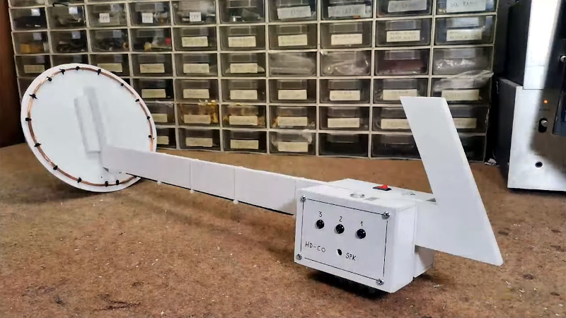
This detector keeps the first oscillator but eschews the second one in favor of an Arduino. The microcontroller acts as a frequency counter, monitoring the frequency and issuing an alarm when it detects a change likely to be caused by a piece of metal. It may not have some of the finess a human ear could apply to a beat frequency in the all-analogue days, but it’s simple enough to build and it avoids the need for calibration. Seeing it in the video below the break we’re sure that just like those transistor models old, there will be plenty of fun to be had with it.
An Arduino may be one of the current go-to parts, but will it ever displace the 555? Perhaps not in the world of metal detectors!


I’ve never tried one, but I wonder if metal detection can be done effectively without an oscillator? Why not have an external frequency source (e.g. a free-running counter output from a micro) drive an LC tuned circuit like the classic detector, but now it uses the change in amplitude due to the presence of an external metal object affecting the EM field of the sense coil. Amplitudes are easy to “sense” (i.e. via micro’s ADC) by “detection” of the pass-thru stimulus signal (diode and capacitor). They operate by the same principles, it’s just not necessary to use the oscillator (well, the micro uses some kind of oscillator, but that’s more precise if it’s using a crystal oscillator).
It’s easier to hear changes in frequency than amplitude variation.
Easier to hear frequency changes. Easier to detect (in electronics) the amplitude variation.
Choose your challenge, I guess.
When I first read about metal detectors, you weren’t going to find a computer that was portable enough for metal detecting.
When they first appeared for military use, you weren’t going to find a digital computer at all.
Arduino ADC is usable around 10/12 bits. That means it can measure up to 1024/4096 diferent voltage levels.
Counting frequency instead can let you choose your own diferent measurement levels (higher resolution). Because it is up to you, what frequency would the oscillator work, and what sampling rate you are going to use.
Perhaps using a 24 bit ADC would make a fair game against frequency count, but it seems to me that this is like comparing AM to FM. Imagine how the tiny noise would affect the end reading, versus just counting cycles.
But the micro is doing the “hearing” with its ADC, right? And if a 10 bit ATMega328 ADC isn’t up to the task, then a 12 bit ARM micro ADC will be pretty good (resolution of 0.0244% of full scale). That’s the reason for the switch and the simpler 2-component tuned circuit (LC) should be more stable too and easy to “calibrate” with the micro.
No need for high resolution. I built and programmed my own metal detector and was summing hundreds of ADC measurements and comparing that to the previous sum many times a second. Plenty fast enough for a human.
What do you mean by “summing hundreds of ADC measurements..”? Summing doesn’t improve resolution. There are lots of constraints to do that, namely: its ADC noise must be zero mean Gaussian, and you need to average a number of measurements (it can be a moving average with a sliding sample window), but averaging reduces the bandwidth since it’s effectively a type of low pass filter. You must rectify the AC signal (envelope detect) to measure it’s amplitude otherwise you need to ensure your sampling at a speed that at least 2.6 times the signal’s highest frequency to comply with Nyquist rules, and “averaging” gets more difficult.
That’s the point. You don’t need to improve resolution. You are just detecting the change as you slowly move the coils over a piece of metal and raising (nonferrous) or lowering(ferrous) a tone.
If you produced tens of thousands of precise readings a second what would you do with them?
Hook up the oscillator to a PLL. The change in VCO voltage = change in frequency. Use a meter and microcontroller needed.
But a PLL tracks another frequency based on a reference frequency. To do that, it uses a phase detector, which is all you need to see the difference. The PLL also low pass filters the loop error voltage to drive the oscillator, which is what I think you’re referring to.