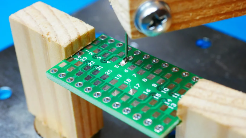
We don’t see too many wooden projects around these parts, but when [olikraus] turned a few pieces of scrap lumber into a functional SMD vise, how could we not take notice? The idea is simple. Two pieces of wood with slots in them hold the PCB. Two other pieces form an arm with an adjustable needle that can hold down tiny parts while you solder. Magnets hold each piece to a metal working surface. Simple and elegant.
We might have 3D printed some of the pieces, but then again, you have to be careful where your soldering iron goes if you go that route. The other advantage to using wood is that you can easily grab a few pieces of scrap and have a different-sized vice in just a few minutes.
There are a few improvements we might suggest. For example, a thumbscrew to fix the needle would be welcome. It seems like you could make the part that holds the needle smaller, too, to help you get your soldering iron into the same area. But it looks workable with no changes at all.
Working with scrap wood isn’t glamorous, but it does make for quick and easy functional builds. A number of the holes and bolts here could even be replaced with glue if you don’t mind the time for it to set.
Of course, you could mix and match this with other designs. We like the “dollar store PCB holder,” but it would work well with the arm from this project. We couldn’t help but think of the SMD beak when we saw this project.


Neat, I am using kapton tape to old tje smd components, the rare times when I solder smd but this seems so much better…
Is this for those with unsteady hands? I’ve found pointy tweezers to work just fine for soldering, and by the looks of it. quite a lot faster too.
Not everyone was blessed with the surgeon’s hands
True. My father used superglue for SMD parts sometimes, I remember. It’s not the most professional way, maybe, but it qualifies as a quick “hack” sort of. ;)
It looks to me like you’d have to have mighty steady hands to aim that “vise” at the part you are trying to clamp – then not bump it while you reach for the soldering iron and the solder.
Tweezers, man, tweezers.
– Brace your hands and arms on the edge of the workbench
– Put solder on one pad.
– Pick up the iron in one hand and the part with the tweezers in the other.
– Place the part with one end on the tinned pad.
– Touch the tip of the hot iron to the tinned pad.
– Melt the solder.
– Remove the iron.
– Let go of the part. It is stuck to the pad.
– Put down tweezers.
– Pick up solder.
– Put the tip of the iron on the other pad.
– Touch the solder to the hot pad – solder melts.
– Remove the solder.
– Remove the iron.
– Touch up the first pad.
This is not rocket science, and it doesn’t require “surgeon’s hands.” It just requires that you actually touch the workbench with both forearms while working.
This is what I do and I can reliably solder 0402s (though nowadays I typically ask JLCPCB to assemble all my passives and available ASICs. I simply don’t have time to waste on soldering passives). However, many people have shaky hands, and no amount of technique can overcome many kinds/severities of tremors enough to allow soldering of smaller parts. The “surgeon’s hand’s” thing is often a little bit of hyperbole to hide frustration with that fact.
With this thing, you can place an SMD piece, tap it around with shaky hands (at the “ends” of their shaking) until it’s right, pin it, and solder both sides with an iron (again, at the “ends” of the shakes). No coordinated, relatively still usage of both hands needed. If I had a tremor I’d be even more inclined to spring for assembly (though it’s relaly pretty cheap nowadays), but some people like to overcome adversity.
I solder SMD parts as I described it above. I can to 0201 when needed.
A tremor in your hands shouldn’t matter. Your hands should be resting on the workbench while you are soldering SMD parts. Only your fingers should be free to move.
I don’t have my PCBs assembled. I enjoy the “work” of soldering things together myself.
@Joseph Eoff you should get out of your “ME! ME! ME!” bubble and watch how shaky hands some people have. It’s not a joke. I know some…
“Your hands should be resting on the workbench while you are soldering SMD parts. Only your fingers should be free to move.” shows your fundamental lack of understanding how much shaking hands affect peoples lives.
They just can’t!!! do some things you can. Not even with your step by step explanation. Period.
@JanW:
If someone’s hands shake that badly, then I don’t see how this vise would help. It seems to me that it would be impossible to set up the vise to hold the SMD part at all. The problem is the same: You have to use your hands to align the parts. If they are so shaky that soldering is a problem, then they’d be so shaky that you couldn’t place the part and line up the little pin on the vise.
It is true that I don’t know anyone who has exceedingly shaky hands. On the other hand, I don’t consider myself to have exceptionally steady hands, either. I have to brace my hands on the worksurface to do fine work.
Solder with flux core must be applied to both PCB and part simultaneously to remove oxidation from both parts and also not to burn out in meantime but perhaps you pre-apply flux and tin on both parts separately?
But that does not work for multi pin parts like 32TQFP 0.5mm pitch which can be comfortably and quickly soldered by hand by using flux galore but only once it’s positioned and fixed correctly.
Solder one end with just the solder on the pad. Solder other end, applying solder to the pad and the part. Resolder the first pad.
TQFP works the same way. Tack down one pin, align the part, tack down a second pin. Properly solder all the other pins, resolder the first two.
I use a way simpler solution: no coffee in the morning but tea. Gone are the shakes.
Yessir, this is a hack. Use what you have and keep it simple. I give it 5 reattached thumbs-up.
In my 20 years of professional career I’ve never needed anything like that despite the fact that I usually assemble every very first prototype myself regardless of current trend of letting it screw someone else. I went through soldering SMDs with micro soldering iron, hot air, IR and I’m pretty sure that something like that on the picture would definitely ruin my productivity and also quality of assembly.
I like it.
Agree
With soldering smt you usually do not have enough hands to hold both the iron, tweezer and solder.
A method I used successfully is:
1. Heat each the “rightside” pad of all footprints and add a bit of solder, do this as quick as possible so less flux boils off.
2. Hold the SMT pad with tweezers, push gently down and reheat the solder to solder one side.
3. Rotate the PCB or put the solder iron i your other hand and solder the other pads normally.
4. Verify and revisit the first half of the pads. you may have had too little solder or flux for a good connection.
I rather like this. How about the stylus arm from an old turntable? Especially the ones with adjustable weights.
I have a piece of plywood clamped horizontally to an upper workbench shelf. The plywood has some holes oversized for fiberglass arrow shafts. The shafts have various kinds of pogo pins. I can position them and let the weight of the shaft do the holding. Forceps are still better for the smallest parts using the method of wetting the PCB pads with solder then holding the part in place and touch the iron’s tip to the joint.
I run some wire wrap wire up some of the shafts from pogo pins so I can also have probes that I don’t have to hold.
There is no need for an adjustable weight,as long as it’s within some reason.
Try this:
1. Take some long nose pliers, a toothpick and a rubber band.
2. put the toothpick in between the beaks.
3. Fixate it with the rubber band (or some tape, whatever).
4. put the handle bars on the table, and the toothpick on your SMT part.
The weight of the pliers is plenty, and because it’s just standing on your desk it’s easy to move or lift. This works better then the magnet thing contraption from this hackaday article.
As a variant:
You can clamp an oscilloscope probe this way too. You can then just set it on a connection and it will stay there reasonably well.
Thank you!
I was going to say: https://hackaday.com/2015/02/05/diy-smd-twofer-manual-pick-and-place-and-the-beak/ but then, of course, Al already had! :) It’s basically a purpose-built version of your plier trick, if I understand it.
Weight on the probe tip / part holder is the best solution, IMO. Gravity works everywhere, so it’s easy to pick up and move, doesn’t get in the way, and doesn’t require a metal surface underneath.
I really like your idea of clamping a scope probe and just leaning it on the part. I think I can overcomplicate that in a clever way…
That metal contraption on that 2015 article is indeed the same Idea.
A triangular piece of plywood with a nail hammered though it also works.
And indeed, gravity works good for this. It works anywhere on your desk, you don’t need magnetic plates or other complications such as elastic bands that will also get pulled sideways.
A disadvantage is the contraption is relatively big.
A similar method that can work with multiple probes is this:
First make something that looks like:
1. put your elbow on the desk, with the underarm straight up.
2. bow your wrist and spread your fingers in a horizontal plane.
You can now set a straight stick on your desk, and rest the other end in between your fingers. You can make sticks that hold Oscilloscope probes, DMM probes etc.
When using sowing needles on the end of the stick, you can for example make logic analyser probes to probe multiple pins of 0.5mm QFP’s.
Another method for logic analyser probes:
Take a dual row male IDC header, and solder enameled wires to it. (I like thin 0.2mm wires)
Clamp the connector to your PCB, or use a small dab of hot glue. It should be strong enough to survive some mating cycles with an IDC flatcable.
Solder the other ends of the enameled wires to your points of interest.
This is quite robust even if you move the PCB around. because there is no relative movement of the parts.
Put the part holder arm on a hinge with a rubber band used for downward force. Otherwise the same with adjustable pin height to make sure the force is normal to the PCB.