Before there were home computers, among the hottest pieces of consumer technology to own was a pocket calculator. In the early 1970s a series of exciting new chips appeared which allowed the impossible to become the affordable, and suddenly anyone with a bit of cash could have one.
Perhaps one of the more common series of chips came from Texas instruments, and it’s one of these from which [Veniamin Ilmer] has retrieved the ROM contents. In a way there’s nothing new here as the code is well known, it’s the way it was done which is of interest. A photo of the die was analysed, and with a bit of detective work the code could be deduced merely from the picture.
These chips were dedicated calculators, but under the hood they were simple pre-programmed microcontrollers. Identifying the ROM area of the chip was thus relatively straightforward, but some more detective work lay in getting to the bottom of how it could be decoded before the code could be verified. So yes, it’s possible to read code from an early 1970s chip by looking at a photograph.
A very similar chip to this one was famously reprogrammed with scientific functions to form the heart of the inexpensive Sinclair Cambridge Scientific.


Interesting, but… how is he converting the image to a bitmap (IYSWIM…) – I can’t help but think from the text that he’s doing it manually!
Go to the github link and read write up. He explained it.
From what I read he struggled to understand the ROM layout, eventually got some pointers from reddit, and was able to identify several of the 11-bit words. That’s where he left it. Not to diminish his work, but I didn’t see anything about using any sort of image processing (or similar) to extract the entire ROM contents from the chip photo, once he figured out the mapping.
Interesting, members of the MAME team been doing this for over a decade at this point. There are countless vintage microcontrollers that have been decapsulated, imaged, and then had the bits optically read out.
Arcade game manufacturers in particular were fond of using read-protected microcontrollers as a form of copy protection – examples range from using a Z180 MCU to drive sound effects and music on certain Toaplan shoot ’em ups, a 68705 MCU on Bubble Bobble for various aspects of gameplay, large amounts of gameplay logic and stage progression are handled for Operation Wolf by Taito’s custom “C-Chip” which ended up being a microcontroller and several other dies in one epoxy package, all the way down to simple key exchanges on various other arcade boards.
The first 5-10 Game & Watch games that were emulated, too, were dumped optically; it wasn’t until later that a method for consistently reading out the contents of the microcontroller using test mode was discovered.
Visually I don’t see the difference between a 1 or a 0. But the decoding addresses part is interesting to read.
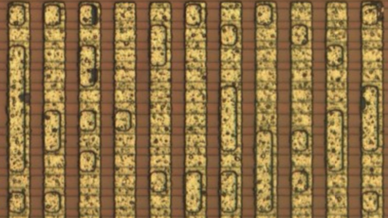
Just looking at the article image, I’m thinking that (much like a CD), a “pit” would be a 1, and a “land” (not a pit) would be a 0. Thus the first column showing in the header image would read 1011111101…
Knowing the encoding would translate it to the correct output.
This is how chip clones get produced if you ever wondered
Stare at a microscopic motherboard and draw a schematic based on photographs
It’s a little amusing to think of doing that to more modern processors. We had an AT&T 8088 (8086 clone) back in the day, and while I am not old enough to have lived through a moon landing, it’s still something to think that chips have gone from something a person with a binocular microscope and a very steady hand could almost draw traces on to scale, to something that requires a significantly good electron microscope to get any detail from. And who knows, I may yet see a moon landing.
Also, if you made a movie about the history of built in storage, would it be a ROMcom?
I’ll see myself out.
I´d love to see a piece of software that – from pictures – would automatically identify chips, PCB tracks and create a netlist + BOM from it, as well as recreate the PCB
And another one to reverse engineer dies like this one.
Except the “put an image as background” feature of KiCAD, i did not see much software for reverse engineering yet…
Not really new… Sean Riddle is doing this for a long time by now. https://seanriddle.com/decap.html
He even has a TMS-1000 Decap -> Bitmap -> Emulator process in place AFAIK…
True, this is nothing new. What is interesting, is the github documents. A useful guide to show what works, and what doesn’t.
wasn’t this done 15 years ago by Major Malfunction
http://visual6502.org/
Article says….
“These chips were dedicated calculators, but under the hood they were simple pre-programmed microcontrollers.”
I kinda disagree with this characterization. I’d say that microcontrollers _evolved_ from these early calculator chips, not vice-versa.
Calculators have a very minimal serial BCD-optimized ALU intermixed with display refresh.
The I/O is specialized for digit display output and keyboard input.