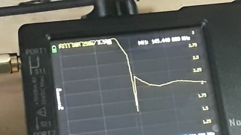
When you buy a cheap ham radio handy-talkie, you usually get a little “rubber ducky” antenna with it. You can also buy many replacement ones that are at least longer. But how good are they? [Learnelectronics] wanted to know, too, so he broke out his NanoVNA and found out that they were all bad, although some were worse than others. You can see the results in the — sometimes fuzzy — video below.
Of course, bad is in the eye of the beholder and you probably suspected that most of them weren’t super great, but they do seem especially bad. So much so, that, at first, he suspected he was doing something wrong. The SWR was high all across the bands the antennas targeted.
It won’t come as a surprise to find that making an antenna work at 2 meters and 70 centimeters probably isn’t that easy. In addition, it is hard to imagine the little stubby antenna the size of your thumb could work well no matter what. Still, you’d think at least the longer antennas would be a little better.
Hams have had SWR meters for years, of course. But it sure is handy to be able to connect an antenna and see its performance over a wide band of frequencies. Some of the antennas weren’t bad on the UHF band. That makes sense because the antenna is physically larger but at VHF the size didn’t seem a big difference.
He even showed up a little real-world testing and, as you might predict, the test results did not lie. However, only the smallest antenna was totally unable to hit the local repeater.
Of course, you can always make your own antenna. It doesn’t have to take much.


I’m willing to bet that most of those cheap VHF/UHF handhelds are bought globally by small businesses for cheap short-range communications, mostly at UHF, so the stock antennae are usually adequate. Hams intending to use these for VHF are more likely to upgrade the antenna.
I think IMSA guy or something did a review of two antennas using the nanoVNA and shows that one was ok, the other nearly identical one totally counterfeit and useless. When buying off eBay or whatever you roll the dice. For my antennas I bought them (gasp. Didn’t make my own) from reputable location with good return policy. I’ve been happy.
Next you’re going to tell me this Baofeng from wish.com doesn’t actually have 9000 watts of “Larger Pweor.”
Guess you missed the mega micro decimal point before the 9 in the advert. Baofeng. Lol. Looks like a yaesu but …
I saw the Imsai guy video, I find it kinda bizarre that you can buy a ‘fake’ antenna that when you tear it down has all the necessary bits to make a halfway decent antenna but they’ve just not…
In China testing products costs a lot more than their production. I have been burned by a mp3 pocket player which is astounding quality-wise; very solidly built, sound is excellent and battery duration fantastic, but its firmware is a joke, the FM radio output is like 20 times louder than mp3 music; even keeping volume at 1 can be too loud in some contexts; also the reception suffers from all sort of noises when screen backlight is on. It is clear to me that it was designed and produced but never tested, not even for 5 minutes.
I don’t think the manufacturers care about making antennas to spec for the frequencies they’re going to be used for. Even in our own bands, most antennas are built to be somewhat broad banded so as to at least put out SOME signal on all frequencies in the band. Since hams tend to go to a lot of frequencies, this sort of makes sense. If you’re going to build your own antenna say, for APRS where you’re on one frequency, then you would cut the antenna for that specific frequency. I don’t think there’s anything that’s the “perfect” antenna. Even a so-called “perfectly tuned antenna cut for a specific frequency” is going to have some loss.
The best antenna* is the one you have with you.
also “best radio,” “best camera,” etc.
Nope.
If you have 3 things that don’t do the job, none of them are “the best”.
One might be the “least worst” but that is not the same thing as “the best”.
Truth.
Iif you need to communicate then no antenna is a worse choice than a bad antenna, so, of that stark, binary pair of options, the bad antenna is best.
Happy to help.
A handheld transceiver antenna is designed for use ON A HANDHELD! The hand holding the radio and the body attached to it form the counterpoise for the antenna. If you stick that antenna on the end of a piece of coax instead of on a radio held by a human hand on the end of a live arm, then it’s going to measure incorrectly.
Came here to say this. Exactly!
It is like measuring voltage with the minus connected to totally wrong point.
Many times the coaxial cable also has it’s own effect to antenna performance if you are having common current running in your coax. Which is very common.. Sometimes even by design.
The cabling always affects performance.
There is a popular hack floating about (and perhaps featured on HaD too) that if you put a copper ring over the antenna connector with a piece of wire of appropiate length dangling it’ll work as a ground element and improve the characteristics.
Perhaps he should have tried that trick too.
It would be interesting if such tricks were evaluated by a cynic; and over a range of handheld antennas.
It’s called a counterpoise and that principle has been around forever.
But stubby antennas have been forever too, and yet here we have a article about a guy testing them.
And a lot of responses that the person holding the device has an intended effect, which would be slightly emulated with a bit of wire I imagine.
Technically correct, but there’s one big problem.
Handhelds are nolonger made of metal, but cheap plastic.
Just compare let’s say, an Ricofunk RTH-2006, with an Baofeng UV5R.
While the RTH-2006 is also made of plastic (I think), the battery department is made of metal, at least.
It serves as a good ground.
https://www.radiomuseum.org/r/minix_ricofunk_vhf_fm_transceiver_rth_2006.html
Sure, there’s still hand capacity and stuff, but it’s far from ideal.
An antenna with a loading coil or a telescope antenna would be more elegant.
The latter can be extended to “full” lenght while the handheld is being used.
At VHF/UHF hand capacity pretty much does the job … a direct connection isn’t necessary.
Baofeng UV-5R is a chunk of aluminum, as well as many other radios. The only ones I’ve seen that were entirely plastic are the small frs walkie-talkie type things.
Yea…this guy clearly has NO IDEA how to do the test.
“He does not know what he does not know”
Something known as the Dunning Kruger effect which is seen in its best use case on the far right and far left of the political Spectrum
Suggested methodology: antenna directly on the NanoVNA and hold it in your hand. I’ve done this same test (and I’m probably now obligated to make a watchable video) and I can confirm that small and medium antennas are garbage for everything, I don’t even know why I haven’t thrown them out. But the Abree 711’s that I’ve had on four different Baofengs over the years all seemed to be far less than horrible on both 2M and 70cm when thrown in the NanoVNA, and in the field they regularly hit repeaters at 70 miles. Hearing back is another story, as these cheap radios are extremely susceptible to “Desensitization” from adjacent VHF transmissions this requiring a filter.
Here’s their web page for their antennas.
https://www.abbree.cn/?s=Antenna
That is exactly correct. The antenna on a handheld can be measured and it’s simple to do but requires surgery. Cut the connection to the RF at the inside of the radio as it attaches to the antenna, run your measurement coax through the inside of the radio through the case, re-assemble the case, hold the radio in your hand and perform the return loss on the integrated hand plus radio case plus antenna combination. Measuring a whip antenna attached to a length of coax is meaningless because it ignores the (in a matter of speaking) ground plane counterpoise effect of the users hand and the structure of the handheld radio.
So a real measurement would be to modify the radio to incorporate the coax measurement point at the antenna connector, run a return loss on an open circuit to the connector, run a return loss on a shorted connector, run the return loss on a precision 50 ohm load ( to calibrate out the effects of the measurement coax) and then measure the return loss of the antenna. But that’s return loss. On a short piece of whip antenna the real measurement would include a calibrated measurement antenna at a calibrated distance to determine radiation efficiency.
To get it correct, IMHO, calibrating out the measurement coax and radiation efficiency requires a lot more horsepower than you get with a cheap VNA. Needs at least a scalar network analyzer with endpoint calibration capabilities.
Someone who actually knows lab testing methodology, thank you!
Also the NanoVNA is a toy along with these inexpensive HTs.
Glad SOMEONE finally applied some test-lab thinking to this.
I routinely see all kinds of antenna/VNA/Rigexpert tests done on Yat, and you can see that the tests aren’t done carefully, replicate-ably, or most often, fail to take local conditions and variances coming from the test environment.
And that is ESPECIALLY true of antennas that were designed to work while connected TO the intended equipment….and which are being tested NOT on the equipment.
Well said. But using an internally battery powered nanoVNA, also held in same hand, could do a useful measurement. Has anyone tried this to prove this point?
I can make you an antenna that will measure perfectly, but be an awful antenna. It’s also called a resistor, aka a dummy load. But measured like this video measures it, it would be a perfect antenna, despite not being able to radiate or receive anything.
The point is: the SWR measurements he’s making bear little resemblance to antenna performance measurements. A VNA used correctly (which the presenter shows no evidence of) will tell you the antenna input impedance and resonant frequency (if any). It’s a go/no-go test of whether it’s safe to plug into your radio, but tells you almost nothing about its actual performance as an antenna.
That said, an antenna that measures off-scale SWR shows the antenna is not present (either open circuit, not fully seated in the connector, or it has a short circuit), so it’s safe to say it’s a poor antenna, exactly like saying a lamp that doesn’t turn on or blows a fuse when you plug it in is a poor lamp.
Years ago I did warranty repairs for an electronics good importer and they jumped on the CB bandwagon, they had a room filled with returned, faulty goods.
In the piles of gear with faults there were lots of cooked mobile radios because people had wired them reverse polarity or to the mains but the antenna boxes were a marvel.
Among the snapped, bent, mangled antennas there were plenty of return labels from shops stating things like ‘open circuit’, ‘does not measure 50 ohms’ or ‘short circuit’ (usually base antennas)
CBers are known for their stupidity. :D
But seriously, not all of them are the brightest. Some are scarily stupid, seriously. I hadn’t believed it if I hadn’t met them in person.
I’m speaking of experience here, as I’m also a CBer.
Not all of them are like this, however. Some are SWLs or electronic hobbyists who happen to be on 11m, too.
Some CBers I know personally also did get their ham license in the past 5 years.
“I can make you an antenna that will measure perfectly, but be an awful antenna. It’s also called a resistor, aka a dummy load.”
Or a light bulb. I often use this analogy.
Btw, back in the day of tube amps, hams did adjust for maximum radiation rather than best SWR.
That being said, transistor amps can’t be abused in such a way anymore.
Tubes were much more forgiving here.
In the Army radio repair course I attended, they used a 100 watt incandescent light bulb in one class (40 watt RF output) instead of the antenna. It served to show that there is real power going to the antenna (it glowed) and let enough RF out to be received by another radio in the classroom.
“I can make you an antenna that will measure perfectly, but be an awful antenna. It’s also called a resistor, aka a dummy load.”
Yeah, but there are lots of ways you can back that out. I mean, just take the antenna outside over a ground plane and measure the power coming from the sky at night with a decent LNA. At UHF it’s stupid-easy to tell the difference between 300 K and ~100 K, and a 100 K LNA isn’t particularly expensive anymore. You want to go really crazy, get yourself some liquid nitrogen and RF absorber and you can really do a nice job. (I do recognize that the stuff I have available may not be what everyone else does :) ).
Fundamentally if an antenna’s well matched to your load at a frequency and it’s a poor receiver/transmitter, that means it’s lossy, because if an antenna is reciprocal (S21=S12) and lossless (sum of squares of columns =1) you do only need to measure S11 (since 1-S11^2 = S21^2 = S12^2). Reciprocity is usually a solid assumption, lossless isn’t.
So functionally if you care about its transmission efficiency (not its gain pattern!) you just need to do noise figure + S11. Doesn’t tell you where the power’s going, obviously: that’s the gain pattern.
There is very little of practical use to be gained from that video. A VNA only measures input impedance … it doesn’t measure radiative efficiency and as the post above states, it doesn’t measure it in the same way it would be used on a radio held in the hand. A much better test would have been to leave the antennas on the handheld and transmit to a vertical antenna a significant distance away that was feeding an SDR with suitable software.
VNA can perfom S12 (or S21) measurement, You need two same antenna or reference antenna with know gain and patern. The setup must be calibrated and with long cables, so as not to measure in the near field
In practice that’s hard to do with a naked VNA (at least the cheap ones): it requires too much dynamic range. You can add a 30 dB amplifier on the output port (being careful to calibrate it out with a calibrated attenuator too), or you can use a spectrum analyzer with a tracking generator. But expect poor results if you attempt this with an unaugmented NanoVNA.
In practice it’s hard to do, no matter what. Generally the actual setup (cables, surroundings, mounts) end up adding enough uncertainty that trying to carefully calibrate everything else is a bit of a wash. I’m lucky enough that I’ve got an anechoic chamber across from my office, but it’s still tricky even with that.
Nobody … certainly not me … said anything about measuring absolute directivity gain. The video purported to COMPARE antennas, and it incorrectly pretended to translate S12 to gain. It is perfectly possible to COMPARE the gain (and pattern) of two antennas without anything like what you stated. The antennas don’t have to be the same other than having the same polarization, and even the receiver doesn’t have to be calibrated in terms of absolute sensitivity as long as it correctly measures the difference in sensitivity. And the use of “long cables” is a ridiculous idea … the receiver can be placed the required distance from the transmitter and the screen image of the SDR software can simply be recorded for later review.
“The antennas don’t have to be the same other than having the same polarization”
Yes, they do, otherwise you need a calibrated antenna. With two identical antennas as your devices-under-test (DUT) you end up with the square of the transfer function because antennas are usually nearly perfectly reciprocal (S12=S21). Obviously you lose any antenna-to-antenna variation in that case, but generally you can figure that out straight from the S11 variations.
“And the use of “long cables” is a ridiculous idea … the receiver can be placed the required distance from the transmitter”
It’s not ridiculous, although poorly worded: if the receiver/transmitter setup is physically large, it’s going to act to modify things. Cables act to move a physical setup farther away, which is what I read that as (again : poorly worded in my opinion). Downside is that a long cable can still act as a reflection source, but you can deal with that with a tiny bias-tee powered LNA and a smaller cable – preferably a high-isolation LNA, so you don’t need to bother backing out the cable and test equipment’s effects.
I’ve thought about trying to make a very tiny SDR-type setup and just have it save results automatically, but it limits what you can actually actively see during testing.
Generally when doing precision antenna testing, we do it inside an anechoic chamber with only the antennas/amps inside the chamber and the test equipment outside. If we’ve got multiple DUT antennas that are close enough to identical, it’s antenna-to-antenna, otherwise it’s with a reference antenna.
You can do it outside in an open space, obviously, but it always ends up being a little more finicky that way due to the complications of mounts and stuff. Colleagues of mine have done rooftop-to-mountaintop, and that works out really well: do it in a pulsed mode with a scope and you can window out the reflections very easily if the antenna’s not too dispersive.
I do not understand where this nonsense comes from. It is simply not true that you need identical antennas to make COMPARISONS of different antennas. You simply use the same receiving antenna for all measurements of different transmitting antennas. If you position the receiving antenna far enough away from the transmitting antenna (several wavelengths) both antennas (transmitting and receiving) look pretty much like point “sources” to each other and the receive antenna looks the same to the source transmission no matter which transmitting antenna is being used. The ONLY requirement is that the polarization be the same for all antennas. I can … and have … plotted the elevation pattern of one of my amateur radio HF antennas with a 20 inch long dipole mounted under my drone and driven by a small crystal oscillator. I guarantee that those two antennas looked nothing alike and yet the measured pattern matched up very well with the modeled pattern … allowing for the uncertainty of where the RF ground actually was since I can’t accurately measure the soil parameters.
No matter WHAT antennas you use on either end, the field strength follows a square-of-the distance result. That’s basic physics. There is absolutely no need for the antennas to be identical for that to be the case. I cannot imagine where you got that idea.
Again, an ABSOLUTE field strength measurement is not possible without a calibrated setup, but COMPARISON measurements most definitely can be as long as the receiver sensitivity is linear within the range of measurement.
Cables don’t act all to isolate transmitter from receiver. Even cables lying on the ground have the potential for the shield to act like an antenna and couple RF in unwanted ways. It is FAR superior to completely isolate the transmitting and receiving locations by using a recording receiver off several wavelengths away … and a recording receiver is trivial to accomplish with an SDR dongle and suitable software running on a laptop computer.
And yes, of course real world measurements taken outside of an anechoic chamber (which, by the way, I have used in the past for antenna measurements) are vulnerable to all sorts of errors due to possible absorptions and reflections. That holds true for antenna comparison measurements as well, as for example if a longer transmit antenna directs its energy closer to the ground where it can be reflected and give a stronger response than would be the case if the user was higher above ground. An argument could be made that is a desirable real world aspect of a longer antenna … but it doesn’t indicate inherently better efficiency. Doing the tests out in an open field is about as good as you can get without access to an anechoic chamber, but I challenge you or anyone else to explain why an open field isn’t good enough for a practical comparison.
Here’s a little thought experiment that should hopefully convince you how wrong you are. Let’s imagine that we’re out in an open field and you have a receive location 100 meters away from my transmitting location. You can see me but can’t clearly tell what I’m doing.
I have two antennas (A and B) that are different, and you have a third antenna that is completely different from either of my antennas. Maybe I have two different rubber duckies and you have a legitimate ground plane cut for the test frequency.
I make a transmission with antenna A and you record the result. I make the same transmission (same power, same frequency) with antenna B and you record the result. Let’s imagine that that the difference in signal strength you measure is 3 dB, with antenna B being the weaker.
Now I go back to antenna A and reduce the transmit power by 3 dB. You’re going to claim that you can tell whether I made another transmission on antenna B or that I simply reduced the power to antenna A???? Ridiculous.
“It is simply not true that you need identical antennas to make COMPARISONS of different antennas.”
Identical antennas allow you to make absolute measurements, independent of the receive/transmit setup. If you don’t, all you’re really measuring is “this antenna is better than this other one at receiving from this specific source.” If the antenna you’re transmitting from doesn’t necessarily fill the band of the receiving antenna (which can happen if the receiving antenna has a response at a higher order mode), you don’t get a full measure of its performance.
The advantage of identical antennas is that if the antenna’s resonant at frequencies you don’t expect, you’ll see it anyway.
Uh … (in response to your last post) … there is no way any part of that video (the one we’re all responding to) measured anything absolute other than feedpoint impedance in a situation (sans counterpoint) that would never exist anyway. His conclusions are purely objective and therefore … wait for it … COMPARISONS.
What exactly is this “absolute measurement” you refer to anyway? If you are talking about field strength in dB/m you simply need a calibrated receiver and antenna … and the receive antenna STILL DOESN’T NEED TO BE IDENTICAL TO THE TRANSMIT ANTENNA!!!!!
I seriously have no idea why your reactions are so strong.
You’re literally saying the same thing the original person was. You either need 3 antennas (A, B, C) where you compare C transmitting to A and C transmitting to B to get relative gains (which is exactly the “thought experiment” you said above). Or you use 2 identical antennas (so A transmit to A and B transmit to B), transmitting from one to the other, and take the square root of the transfer function, and that gets you the absolute gain of each antenna, which you can directly compare without needing a third antenna at all.
Yes, you don’t need the absolute gain of an antenna to compare them, but if you can get it, that does let you compare them anyway.
If you only have 2 unknown antennas – as in, that’s literally all you have, no additional radio source whatsoever – you can’t compare them because if you transmit from A to B you don’t know if A’s not transmitting or B’s not receiving.
This isn’t some sort of weird Internet hack or something: I guess it’s sometimes called the ‘two-antenna method’ and I wouldn’t even know a source to reference it since it’s like, WW2 era-stuff. I guess here would work?
https://www.ece.mcmaster.ca/faculty/nikolova/antenna_dload/current_lectures/L08_Measure.pdf
From an amateur radio perspective it seems stupid to say that you need a 3rd antenna, because you really just need a constant source, and you’ve probably always got some kind of a source. But that constant source is the third antenna.
I’m frustrated because you keep misrepresenting just about everything. The idea isn’t to use the same antenna to transmit to two different receive antennas … the idea is to use two different antennas to transmit to the same receive antenna. You compare the transmit antennas, not the receive antennas. I.e., in your example, A to C and B to C. C does NOT need to be identical to either A or B to get a valid comparison between the A and B.
With that, I am done trying to convince you of anything. I did this stuff for a living at one point in my career, but you simply refuse to get it.
I agree with Paul. The antenna can’t be properly measured when placed on the end of a length of coax. If you could read VSWR on the HT, it would read completely different. And yes, VSWR is important but it doesn’t necessarily reflect on air performance.
I’ve found that most stock antennas are tuned for 155/465MHz, actually decent for business band use. Makes me wish that 95(j) didn’t prohibit MURS/FRS or MURS/GMRS combo radios. Though, to add to what others have said, many swr meters will recommend adding a piece of wire or sheet metal to HT antennas for an accurate reading.
As others have noted, the VNA isn’t really telling us anything useful, because:
S W R D O E S N ' T M A T T E R
A field strength meter at a distance would have told us more.
And by the way, what is the ground plane for that rubber ducky?
Y O U A R E T H E G R O U N D P L A N E
SWR has very little correlation to the efficiency with which any of those antennas radiate RF. It’s just the measurement of the stored energy in your RF circuit because of impedance mismatches. It starts to be important when you can solve the other problems of the system, like having a full_size antenna with a ground_plane.
And by the way, if you thought small loop HF antennas, which are in general about 5% efficient, were bad, those rubber duckies are just as bad or worse. Both will let you make a lot of contacts, but can’t hold a candle to a full-size antenna with a properly sized ground-plane. That “Miracle Baby” rubber ducky that is 2 inches long? The miracle is that your signal budget still lets you make some contacts. The other miracle is that you paid good money for that.
Compromise antennas are just that. They work, but they’re a compromise. What you are losing is signal strength and antenna pattern.
My great grand pappy always liked to say ” you can have signal strength, or bandwith. Cant have em both.
What about those old coiled in-rubber (I don’t know what to call them) antennas they used on CB handhelds? Those at least were optimized for a longer wavelength.
Still used being made. There’s nothing magical about them in terms of performance, but they get points for mechanical durability.
It’s all about the wavelength. If the antenna isn’t as long as the wavelength, then there’s going to be loss. There’s no way around that.
Dipoles are optimum at about 1/2 wavelength. Monopoles (whips) over a ground plane are optimum at about 1/4 wavelength. The ground plane acts as a mirror, effectively doubling the length.
Reactances can be used to tune shorter lengths, but than increases losses and usually narrows the antenna’s useful bandwidth.
The radiation pattern also might matter to the operator.
Sometimes, a flat radiation pattern is accepted in trade of a high-gain factor, for example.
Other operators do favor a good-omni directional antenna for short distance communication, also. Like CB/11m.
Or a very steep radiation for satellite communication.
1λ is hard to use, the Hertzian dipole (1/2 λ) is the normal reference.
Unless we’re including the isotopic antenna. ;)
On the downside, the dipole is not 50 Ω and can’t* be attached to a coaxial cable directly.
A coaxial stub or an 1:1 balun next to the antenna feed point is required.
This will also match the symmetric/unsymetric ratio (diople vs coax cable).
1/4 antennas.. The 1/4 λ antenna isn’t considered a dipole, really.
Not in my country, at least.
The simple groundplane antenna (1/4 λ) is a classic, since she has an 50 Ω feed point (roughly) and needs no extra ground connection.
Base stations (fire brigade, police, ambulance etc) on VHF/UHF use it, too.
She usually has three counter poise elements, for a good omni-directional radiation.
Her radiation is also very flat like a pancake, so she’s technically not bad for shortwave, either.:
She will hit the E layers easily that way (waves make big jumps).
Bear in mind that a lot of the HT “rubber ducks” are intended to use the moisture in the human body as a capacitive ground plane or other RF electrical “component”. Bench testing them “in situ” can be difficult.
The one gruff Owen Duffy has some words to say about antenna gain measurements:
Calculator: https://owenduffy.net/calc/agctam.htm
A bit of background and commentary in Duffy’s inimitable style: https://owenduffy.net/blog/?p=23608
Yeah, it should be noted the 3-antenna method needs a lot of measurement configurations – 6, ideally, although if your transmitter/receiver (not the antennas, the things generating/receiving the signal) are very well matched and their effects on the setup are isolated you can get away with 3 like in that calculator.
The (explicitly stated) assumption there is that the configuration is purely reciprocal (transmitting from 1 to 2 gets the same result as 2 to 1) which is an extremely good assumption for just the antennas but not the entire configuration.
There’s so, so much that’s confusing here.
As others have mentioned, using SWR for electrically small antennas somewhat misses the point. They’re electrically small. They can’t have a great SWR.
But… Watch the video.
The guy puts on one antenna (the second-to-longest one) with an SWR that actually hits 1.5 and is under 2 for the entirety of 420M-450M.
He then puts on the longest antenna and it’s got an SWR that hits 1.7 and is between 2.0-2.8 from 420-450.
And then promptly says the longest antenna is the best? Am I losing my mind here? What the heck?
Going through the rest of the video (the antenna/equipment fumbling made it hard to zip through to find which antenna was which) the “longest” antenna was significantly better at VHF so maybe that’s his reasoning, but it’s definitely not quite that simple.
“They can’t have a great SWR.”
Well, technically they can – from a transceiver’s point of view.
It just needs a coil (and a capacitance).
A PI filter, so to say. That’s what a matchbox is, in it’s simplest form.
That being said, I think what you meant to say and I do agree.
A very small antenna can’t perform very well.
Sigh, that was a typo, it should’ve said transmission efficiency. All the SWR mentions bouncing around…
I was mainly just confused watching a guy show an SWR for 2 antennas where the first is clearly better than the second… and saying use the second one.
Yeah, with short antennas he’s very wrong to assume that S11/SWR is all that matters since they’re not lossless, but even by his own logic he was saying something wrong. Totally confusing.
(and of course even if you get a ‘good’ transmission efficiency, it’s still just limited by the effective length of the antenna anyway!)
https://www.qsl.net/4nec2/
Good tool .
Very nice, thanks for the link.
You must realize that with the HTs you are a part of the ground. So testing an HT antenna by itself isn’t always going to be good SWRs.
“making an antenna work at 2 meters and 70 centimeters probably isn’t that easy”
Eh, depends. I guarantee if those are the only two things you care about, then you can make one that works well on both bands by mounting a sufficiently large diameter copper pipe of the right length as a vertical over a good large conductive sheet. If it’s a thin wire, you’ll probably find that the best efficiency is on the low end of one band while it’s on the high end of the other.
If you add “must be reasonable to put onto a handheld radio” then I would go for something like the “signal stick” antennas rather than the stubby ones, which tend to have lots of loss even when they are a decent impedance match. You really need to measure the received signal at a remote location for those; you’ll not be able to say for sure which is radiating better otherwise. And yeah, you need to hold the device while testing, because you’re the other half of the antenna when using a handheld the normal way. You can figure out what an antenna’s doing by the look of its vna sweep if you know its design, but the random stubby antennas are a big unknown, and even the complex impedance / smith chart output doesn’t truly prove everything you want on its own.
I’ve also tested all my rubber ducks and other HT antennas I’ve purchased over the years. I used a VNA and a Boonton grid dip meter. Most stock antennas are crap, with a notable exception of the stock antenna that came with my Yaesu VX5 and VX7. Most of the after-market HT antennas were better with the best being the Signal Stick HT antenna. I would suggest that if you buy an HT, especially one of the less expensive ones, you should immediately replace the stock antenna with a good aftermarket one.
Unless your connect the vna to the connector of the radio in place of the radio and decouple the test coax, you are not going to get an accurate idea of the antennas behaviour connected to the radio. Brand name ham gear was pretty good for their transceiver/ antenna combination in the day. The radio body and battery pack are definately part of the antenna as is your hand.
Are you sure the NanoVNA isn’t the problem, it’s supposedly doing what an instrument which costs 10’s of thousands of dollars does.
I have doubts about the accuracy.