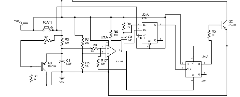
A common theme in modern consumer electronics is having a power button that can be tapped to turn the device on, but needs to be held down when it’s time to shut it off. [R. Jayapal] had noticed a circuit design for this setup when using DC and decided to create a version that could handle AC-powered loads.
The circuit relies on a classic optoisolated triac to switch the AC line, although [R. Jayapal] notes that a relay would also work. The switch circuit consists of two transistors, a comparator, a flip flop and a monostable. As you might expect, the button triggers the flip flops to turn the triac on. However, if you hold the switch for more than a few seconds, a capacitor charges and causes the comparator to trip the output flip flop.
The DC circuit that inspired this one is naturally a bit simpler, although we might have been tempted to simply use the output of that circuit to drive a relay or triac. On the other hand, the circuit is set up to allow you to adjust the time delay easily.
Given the collection of parts, though, we wonder if you couldn’t press some 555s into service for this to further reduce the part count. If relays are too old-fashioned for you, you can always use a solid-state relay or make your own.


Ouch. Kind of just begs for a $0.50 microcontroller, no?
Meh depends on your tastes, myself I like soldering more than typing… Difficult to believe with my constant bloviating, I know.
And it would still require something hooked up to the MC that could handle mains AC
Like an optoisolated triac?
i used one with a few extra parts to turn the thing on, control the device with some extra presses and a long press to turn it of. basically i used one pin from the mcu as a hold signal for the power chip, so as soon as the mcu was booted, it took over from the button to hold the ebable pin high. the mcu monitored the button. short presses used for actuons, long press to disable the hold pin.
switching dc or ac is irrelevant as that is just what you hook up to the digitally controlled pin used for the occasion
I agree, 8 pin micro and your basically done.
The correct rejoinder, as everyone knows, is “could have used a Cray-1 supercomputer”.
Overkill. It just needs to be IoT and run on cloud services to determine on/off intention
(with subscription)
http://www.mosaic-industries.com/embedded-systems/_detail/microcontroller-projects/electronic-circuits/push-button-switch-turn-on/nand-gate-latching-press-on-hold-off-logic-toggle-switch-circuit.png?id=microcontroller-projects:electronic-circuits:push-button-switch-turn-on:latching-toggle-power-switch
Two capacitors, three resistors, one NAND chip with at least two gates. Instant on, press 3 seconds for off.
CD4011BPWR costs 36 cents in single quantity.
Different variations with simple mosfets and auto on/off also available:
http://www.mosaic-industries.com/embedded-systems/microcontroller-projects/electronic-circuits/push-button-switch-turn-on/latching-toggle-power-switch
Not complete; the Vdd (5V) comes from where?
There are dozens (OK. a handful) of Push-On/Push-Off circuits.
My fave : https://breadboardcircuits.com/transistor-push-on-push-off-switch/
I do agree, the Vdd bas to be added to the set up, and overall this design is really juge, not optimal, expensive, … It looks more a High School class exercice. Yet it is sold as practical…
Or, one could use a SPDT switch for rock off, rock on functionality. The latch circuit is simpler, and you avoid the annoying ambiguity of not knowing whether your device is booting or shutting down.
I think I want a triac AND a relay. That way if the triac gets stuck off the relay will do the job. And if the triac does work, there will be almost no current going through the relay, so there shouldn’t be any nasty EMF or arcs.
Of course my design choice make it more complicated, more expensive, and more likely to fail.
Intrigued to hear nobody dincussing inverting the sense of the switch!
Most mains-powered stuff in my world (that doesn’t already have significant computing power) is tools that can injure if they go wrong (washing machite, heater, etc). If anything should have a “are you really sure?” time delay on it, I vote for ‘turning the device on’ to be delayed!
{Insert 555 comment here}
7555 for those concerned about quiescent current.
I recently designed something for my Ender:
It uses a mains rated DPST button that directly powers a 5V supply.
A Pico (cheap, implements other things, too) then powers a relay, that latches the mains to the pushbutton.
The second pole of the pushbutton goes to a nice mains rated optocoupler that needs only two resistors on the mains side, to detect button presses to switch off the supply.
The only downside is, that, for a ACPI like long press force power off, you’d have to think about a way to signal the user to stop pressing the button.
The Pico also drives a little OLED for low level information about the other pico functions like temperature monitoring, fan control, 24V Printer Supply control etc.
I like the possibility to automatically switch off everything to stop wasting energy in standby…