A couple of years ago one of the Hackaday Prize finalists was a project to take highschoolers through building a direct conversion radio receiver for the 40 metre amateur band. It was originated by the SolderSmoke podcast, and we’re pleased to see that they’ve recently put up an overview video taking the viewer through the whole project in detail.
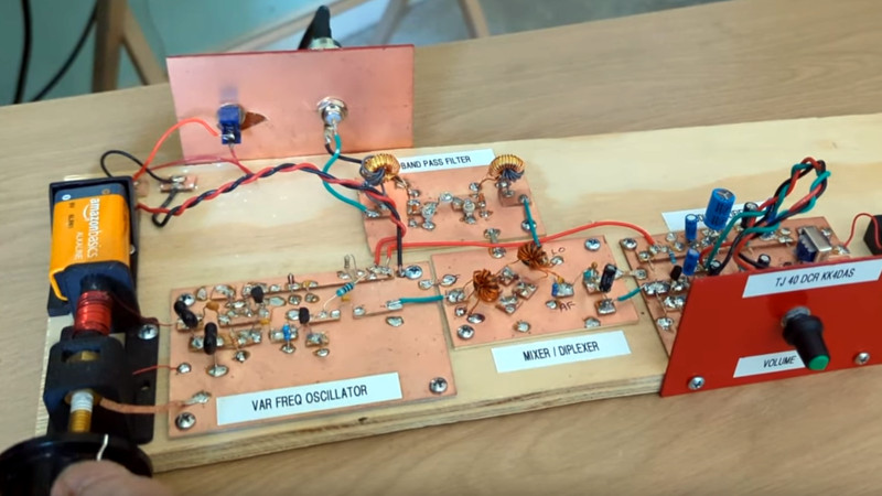
It’s a modular design, with all the constituent building blocks broken out into separate boards on which the circuitry is built Manhattan style. Direct conversion receivers are pretty simple, so that leaves us with only four modules for oscillator, bandpass filter, mixer, and audio amplifier. We particularly like that it’s permeability tuned using a brass screw and an inductor, to make up for the once-ubiquitous variable capacitors now being largely a thing of the past.
A point that resonated was that most radio amateurs never make something like this. Arguments can be made about off-the-shelf rigs and chequebook amateurs, but we’d like to suggest that everyone can benefit from a feel for analogue circuitry even if they rarely have a need for a little receiver like this one. We like this radio, and we hope you will too after seeing the video below the break.
Need reminding? See the Hackaday.io project page, and the Hackaday Prize finalists from that year.


That variable inductor is not “permeability tuned” by the brass. The permeability of brass is pretty much the same as air, and changing the amount of brass inside the coil won’t change the permeability of the space inside the coil to any significant degree.
If the screw were ferrite, the permeability would increase and the frequency would decrease as more material is inserted in the coil.
The brass screw behaves the opposite: adding more metal in the coil decreases the inductance and raises the frequency.
The key is that brass is nonmagnetic and is a conductor: it acts like a shorted winding in the air-core transformer, and that is what is decreasing the inductance.
Spot on.
G7VFY
A good cheap way to make a PTO is by using a ferrite rod (AM RX antenna core), wind your coil around it over a piece of thick paper (like a note card) and just insert to get the desired L. First ATU I made used it with a polyvaricon. Simple quick old school hack.
Yup, they got that bit wrong.
However, it’s still a fun project and I’d probably agree with them that a large percentage of hams have never got their hands dirty by building an RX, those that have probably built a kit.
Heck, these days it’s not a guarantee that a ham owns a soldering iron so anything that encourages technical experience has to be good right?
Does building a crystal radio count? Oatmeal box wrapped in enameled copper and a bit of coffee can lid for a wiper, etc…..elementary school fun!
(Don’t ask about the improvised x-ray machine I built in middle school. Good times ….. 😁)
Crystal radio definitely counts. It’s not the particular skill required that makes the magic; it’s the assembling it on your own and then hearing a radio station.
If you look at the lower left hand side of the board labeled var frequency oscillator you can see see the brass bolt and one end of the coil are both soldered directly to the copper which is most likely ground. What has been done here is that either the coil former but not its frame is ferrite or steel and the brass bolt act as a single winding and it’s position allows more or less of the magnetic field to pass through the bolt or the entire coil former is plastic and the bolt is actually bronze. It is a bolt not a screw since bolts get a nut and screws don’t. Assuming average size for the person in the video I would guess that’s a 1/4 x20 by 3 inch bolt. Brass is used mainly for decoration. Even if it were a sink part it would probably be steel with a brass finish and that would definitely mean it is permeability controlled
He did say the 3D printed the coil former so that would make it plastic. Knowing bolts that is more then likely a steel bolt with a brass finish so you are right on that one.
Interesting speculation, but incorrect.
Brass threaded rod and screws might not be your usual Home Depot fare, but are pretty common. Brass-plated steel 1/4-20 are not.
The nut (and hence the screw) are grounded to avoid parasitic capacitive pickup and detuning when the user’s hand approaches the coil.
There’s an ugly sort of beauty to manhattan-style circuit boards. It doesn’t look pretty, but it doesn’t look wrong either.
This style is new to me, but the basic idea seems familiar.
In my country, we used to use wooden boards and metal thumbtacks.
The thumbtacks serve as soldering points.
Hence the term “breadboard”. It literally refers to a wood board for (formerly!) cutting bread on. We used finishing nails instead of thumbtacks — the original turret terminals.
Radio Shack used to sell “P-Box” kits, with a plastic box that had holes in it. You pushed spring posts into the holes, then used them to mount the components. Lots and lots of us go our start with these kits. God I miss Radio Shack…
Heating up the Iron and using the hands is Real Radio ….if it looks wrong and is an ugly beauty…then it works right ,😜
“A point that resonated was that most radio amateurs never make something like this. Arguments can be made about off-the-shelf rigs and chequebook amateurs, but we’d like to suggest that everyone can benefit from a feel for analogue circuitry even if they rarely have a need for a little receiver like this one. ”
No. Let’s not tell people how they should enjoy their hobby.
I wouldn’t be reading this article if I weren’t interested in this aspect, but I’ve crossed paths with multiple people who think they know how I should enjoy this hobby.
That needs to end.
If we were talking about train sets then we could split up the hobby into two kinds of people. People that like to build the tracks and people that like to play with the trains. There is a huge overlap in what they do, but how they enjoy it greatly differs.
Both are equally important to the people that are selling the tracks and trains, which is a good thing because without people selling tracks and trains… the hobby would be difficult. We all need each other, let’s play nice.
What got me into HF again was the Pixie one-transistor transceiver. Built it on a pice of blank PCB with parts from the lab and used a color burst crystal. Lots of fun.
My condolences. The Tubixie was a better design, IMHO.
The Pixie was bad design, I think. Barely real-world usable, I think.
Like the toys from Mickey Mouse magazine.
Had a couple of them here, because the hams in the neighborhood fell for the Pixie fad.
One ham using it with a switching PSU was so excited hearing “shortwave” signals, but switching to a battery suddenly made these signals go away. I almost cried (innerly).
Then one unit was broken.
Turned out the 386 amp chip from was either broken
or wasn’t able to drive the low impedance walkman headphones (they’re stereo and wired in series).
Replacing it by a 1970s model brought the “TRX” back to life.
But TRX is a bit of a stretch, maybe. It’s a glorified oscillator on a wire antenna.
The receiver part isn’t very good, either.
In the end, using an Yaesu FR-101E from the 1970s was more fun.
I’m an experienced Extra Class amateur. I was interested in Pixie and one for 30m. I got to work and between MA an GA. I still have QSL card. It was a difficult contact. But worked. I experiment with circuit and fun. Isn’t have fun what HAM radio is all about? I still wish I could measure the preformance, I don’t equipment now in retirement. You know in the early days of amateur radio everyone built his own equipment. They didn’t have this wonderful technology we have today. What’s wrong with having fun. If that’s what it is? Don’t knock it.
Ken AE1X
I like this ,how do I get started .please.
What about doing the whole thing using a Texas Instruments DSP processor and an ADC and DAC which means the processing can be done using machine code as basic or python is not fast enough
The point of this project is to expose people to analog electronics. You could swap out the VFO with a digital VFO module from QRP-LABS and replace the rest of it with a DSP, but that’s not the point.
LOL. … total comprehension fail. The whole point of the article was about building an ANALOG receiver.
Maybe the high school kids who had never soldered before would have understood what was happening in that circuit, but chances are far higher they’d understand the circuit they built for this project.
I reckon if they could get through this, then some of Charlie Morse’s projects (zl2ctm) would be a natural stepping stone towards what you’re suggesting. He has different done some great little si5351 and teensy based Software radios using the passing method for modulating and demodulation of single sideband signals. Also some using traditional crystal filters etc.
Do both.
What aboooout lowering the noise floor and MDS at least 20db over anything digital…….
What about LEARNING the underlying theory so you can build one yourself and NOT “cut n paste” but instead actually think for yourself and enjoy the pride of achievement in actual creation versus mindless copying?
If your MDS on a digital rig is 20 dB higher than anything analog, you’re doing it wrong. Simple as that.
K0IYE wrote the BIBLE on this topic over twenty years ago!
“Crystal Sets to Sideband” teaches EVERTHING needed and a whole lot more!
http://www.antentop.org/006html/006_p77.htm
73