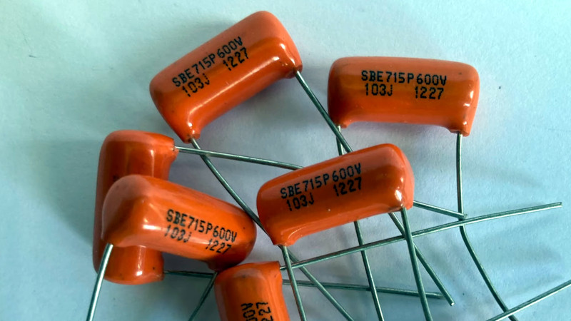
You can work with a part for many decades, and still learn something new about it. At least we can, and we don’t mind admitting it. Take film capacitors — we all know they aren’t a polarized part like an electrolytic capacitor is, but as [TheDannVal] points out, that doesn’t mean both their leads are the same.
This might sound counterintuitive, but if you consider for a moment their construction it makes sense. A film capacitor is made from two strips of foil with a strip of plastic film between then, rolled up tightly into a cylinder. One of the pieces of foil that forms one side of the capacitor ends up on the outside of the cylinder, and thus forms the shield for the other. Thus if that side isn’t connected to the lower impedance side of whichever circuitry it resides in, it can pick up noise, while the inside strip of foil can not. It’s so obvious when demonstrated, but we have to admit to never having considered it before. Some film capacitors have a line marked on them to denote the connection forming the shield, for those that don’t he provides a couple of methods for detecting it.
The full video is below the break, and maybe you too can now pay attention to your capacitors for lower noise audio circuitry.


Ahh yes the dropper power supply capacitor
I rarely see them anywhere else
Anyone familiar with tube circuits likely knows about this. It’s the same as with paper capacitors.
I thought it was more common knowledge too. Good to see it still being taught.
Surprise everyone. Inductors are the same and you can solve EMC issues by just turning them 180deg on the PCB… Some companies even marketing this fact!
I may be missing something, but I don’t see why an unshielded axial inductor would have any directionality. Why does it?
Some axial inductors stand up, and having the end in the air connected to a noise-sensitive node can cause problems. Also, some inductors have multi-layer windings, and the lead connected to the outer layer may pick up more noise.
I never really gave much thought to it before.
It is so obvious to understand when one stops to think about it. Thanks for taking the time to share.
Mr.Carlson knew.
I don’t follow this. We want the inner plate to be on the output side either way?
It depends on the circuit. Whichever side has least impedance to ground gets the outer foil. That’s easy for bypass caps with one side grounded. For coupling caps a good circuit is designed with both sides equal, so it doesn’t make a difference.
Who knew? I did! I did!
BTW, of course this applies to paper capacitors as well – not that there are so many of those about any more. Also, it applies to those epoxy-coated polyester and Mylar capacitors which look Chiclets with two wires sticking out of one narrow side. The flatness of these tends to hide the fact that they are also wound.
Some wound capacitors have “polarity” bars on them even though they aren’t polarized in the usual sense. Does anybody here know why the indicator isn’t universally applied to them? Maybe because they’re expected to be used in power bypass or large-signal circuits where it doesn’t really matter?
I assume this only applies to roll film capacitors as stacked film capacitors don’t have this property. They’re atacked abababab, not abababa, so you always have that symmetry.
Not unless you run the ground plane under the smd capacitor. Not sure it’ll make a ton of difference since the component is so small and those thin layers hardly block any EMI.
I don’t know why you mention SMT as we’re talking leaded parts here. Stacked film caps are made from alternating layers of metalized plastic which compose the two sets of plates.
I learned this years ago while i was watching quitar amp repair videos. I think one of those guys did a video on this.
Back in the good old days of high end audio, we used a lot of axial film polystyrene capacitors. They were often marked with a red or yellow colour on one end, specifically for this purpose of identifying the outermost layer. When we were using those big black round things for music (LPs) with a moving coil cartridge generating, ooh, 3mV of signal it was important to avoid noise sources – especially if they were as easily avoidable as putting capacitors in the right way round.
Polystyrene caps seem to be in very short supply now, and definitely not in SMT since they melt unless hand soldered.
Polystyrene are like gold. Great for use in LC VFO’s for their temperature coefficient.
Mr.Carlson demonstrated this on his YT channel years ago. Surprised that most commenters were not aware.
That’s where I learned about the foil side too. I thought it was more well known.
The demonstration is true but is a huge exaggeration.
These caps are inside an equipment surrounded by a grounded metallic chassis, pretty much making the orientation irrelevant. People don’t play guitar while their finger is inside, touching these components; also there’s no switching mode phone charger inside the guitar amp.
It still does matter if you are really trying for minimum noise. 60Hz filament supply, ripple on Plate supplies, possible unwanted feedback, anything that can couple into low level high impedance signal paths.
I’m waiting for the youtube video that shows the difference of a reversed capacitor in an actual real-world situation (e.g. within a metal chassis, proper construction, no artificial noise sources).
Well typically in a guitar, one side of the capacitor is connected to the guitar’s “ground” and the guitarist’s fingers are touching that.
Actually the traditional electric guitar design leaves a lot to be desired. I don’t think anyone would do anything like that starting from a clean sheet.
Says the guy whose never worked on a 1950s Johnson transmitter.
As seen here: https://hackaday.com/2015/05/20/how-to-tell-if-youre-installing-foil-capacitors-backwards/
(Yes, Mr. Carlson)
Thanks for the link. Didn’t know Mr Carlson. Great find.
This must affect the Stratocaster’s most popular mod: the treble bleed. It’s basically a cap and resister in serial on a volume pot to let some treble through when volume is turned down part way.
Err, parallel, but if you know the treble bleed mod, you know exactly what I mean.
In older Tube (valve) audio equipment it was normal to have 3 wire paper capacitors, stage decoupling, especially feeding potentiometers for volume and tone shaping. Normally paper, they were not only polarised but had a foil screen wrapped around them which was strapped to earth.
Who knew? About everybody working with vintage equipment…. And a lot more. This is like hearing water is wet.
I didn’t, but then the most vintage equipment I work with are 1980s microcomputers, so not a lot of analog. So I’ve learned something today.
Relevant xkcd: https://xkcd.com/1053/
I didn’t.
Although Though I know that water is wet, I never had to be concerned with circuits highly sensitive to surrounding noise in my electronic projects.
So I learned something today. Might come handy one day.
A lot of audiophile now have one more excuse for being unhappy with their systems, start tinkering and then report huge benefits. Well done :))
Similarly, when connecting a series of R and C to ground, e.g. in a PLL loop filter, it is better to connect the C to ground instead of the R, even though, according to Kirchoff’s laws, there is no difference.